Detailed view of Hosts and Business Processes
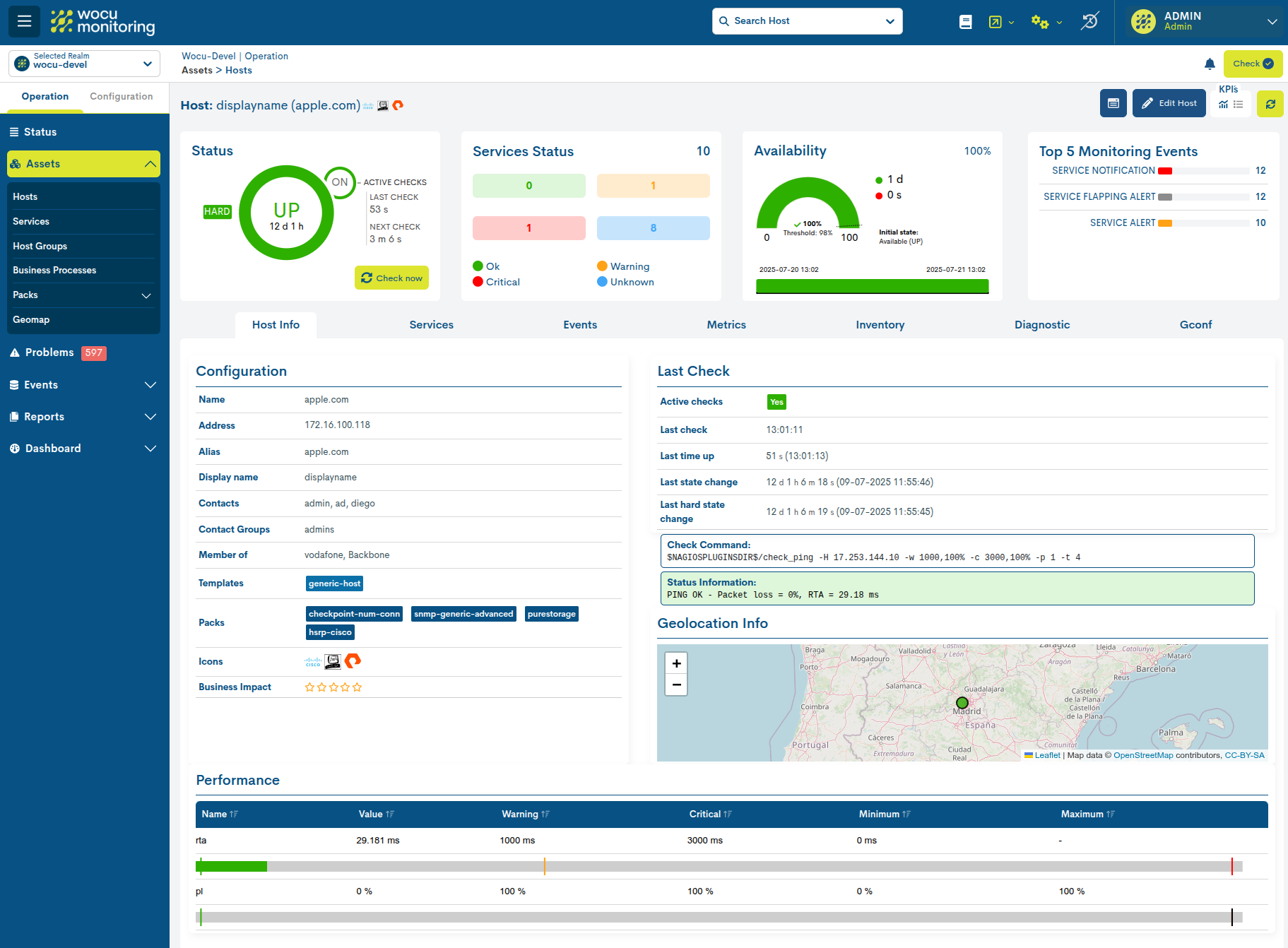
The Host and BP Detail View allows the user to directly access detailed, complete, and up-to-date information about the Hosts and Business Processes (hereinafter BP) monitored in WOCU-Monitoring. All this information is collected over the last 24 hours and is displayed between the fixed KPI`s and the following sections:
Access to sight
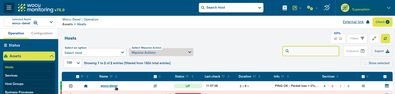
The detailed view of a Host is accessible from the various Host names available throughout the application. These names act as navigation links. Clicking on any of them opens the corresponding detailed view of the selected Host, where you can view its status, services, metrics, events, and other associated information.
See the following example, corresponding to the global list of Hosts. In this case, access to the details view is achieved by clicking on the device name available in the Name column.
Host Selector
In this view, the device name is displayed within a drop-down selector located in the header.
When expanded, WOCU-Monitoring displays the set of Hosts belonging to the currently selected Realm. To access another device, simply select its name in the list; the view will automatically update, displaying the information corresponding to the new Host.
Each element of the selector also incorporates a status indicatorusing a colored dot, allowing you to visually know the “”current monitoring status of the device before accessing its “”details. In this way, the user can quickly navigate through the “”different assets of the Realm and detect those with relevant “”states without leaving the details view.

Icons identifying Monitoring Packs
Next to the Host selector, WOCU-Monitoring can display identifying icons associated with the Monitoring Packs applied to the device. These icons help quickly recognize technologies, manufacturers, operating systems, or other relevant characteristics of the monitoring profile. The icons are only displayed when the device has associated Packs.
The system presents a maximum of three icons, prioritizing those considered most representative and least generic according to a predefined weight scale.

Note
The Pack icons and the selector serve different functions. The selector allows you to navigate between Hosts, while the icons provide visual information about the technology or monitoring profile associated with the selected item.
KPI`s
This space displays a series of dashboards with key performance indicators and operational statuses of the Device or BP in question. The data is displayed across four panels and is compiled over the past 24 hours.
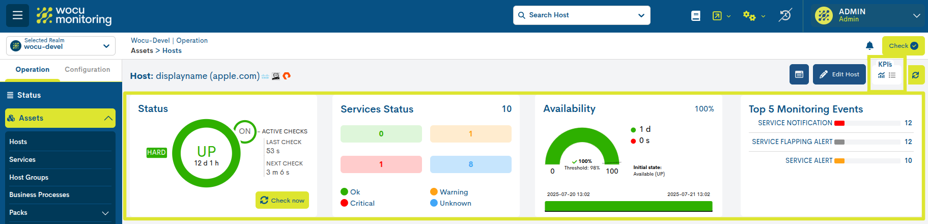
KPIs can be viewed in two possible ways:
Full view
By activating the icon marked in the following image, the following KPIs are displayed, with detailed data and interactive graphs:
Status
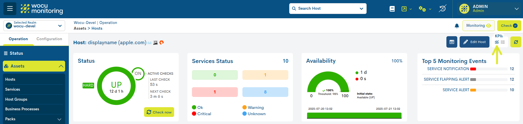
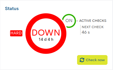
This first panel indicates the operating status of the host and the monitoring checks performed on it. In addition, other complementary data is provided as explained below.
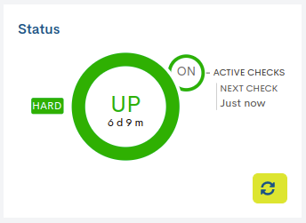
- ✓ Current host monitoring status and active time
Inside the central circle is indicated: the state that the host records and the total time that the current state has been active. In the previous image, the host has been in UP state for six days and nine minutes.
The rapid alternation of state changes in a host is known as Flapping. It is also represented on the panel by a yellow half-circle with a flashing grey arrow inside it.
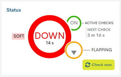
- ✓ Monitoring Check: Active Checks/ Next Check
WOCU-Monitoring performs checks to assess the operational status of the host.
The smaller circle ON/OFF, located next to the label Active Checks, indicates whether the check option is activated or deactivated. Additionally, the label Next Check shows the time remaining for the next check. In the image above this function is enabled and the next check will be performed in twenty seconds (“Next check: 20 s”).
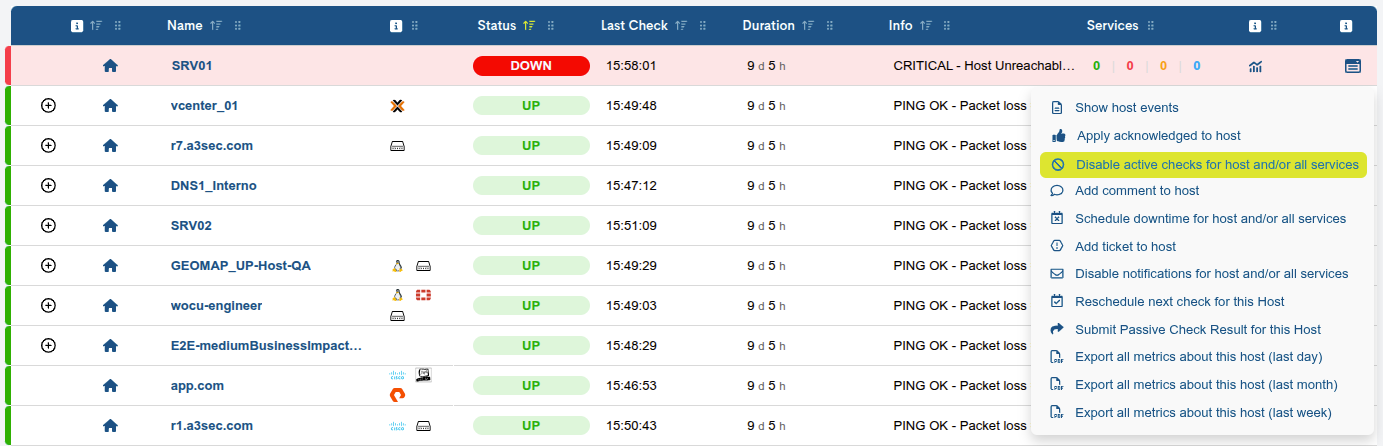
The option to disable host monitoring checks, is accessible from the Disable active checks action within Actions on inventoried hosts (ℹ).
Soft and Hard States
Related to the checking task, this panel also offers additional information about the types of statuses obtained and their severity level, using the following labels:
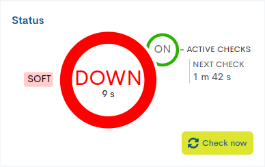
Soft: is assigned when the host status obtained is not definitive, as it may or may not be reverted in the next check attempt. In the case of exceeding the predefined number of attempts, obtaining negative statuses, the error severity level will be raised to HARD type. The objective is to avoid false alarms due to transient problems.
Hard: is assigned when the host status obtained is continuously erroneous, without being corrected. That is, when the host returns a negative status on the first attempt and also on subsequent checks, exceeding the predefined number of attempts. This new situation is notified to the contact user.
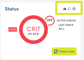
✓ Icons of actions applied to the device
When a device has actions enabled or running, the widget will display icons representing each action. These icons allow you to quickly identify which actions are active at any given time, providing an immediate and clear view of the device’s operational status.
The possible actions are explained in the following section: Actions on the Device.
Services Status
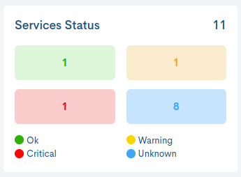
This panel displays a count of services based on the current monitoring state. The total number of services associated with the host is listed in the upper right corner. The legend identifies each of the different states defined by the system.
Availability
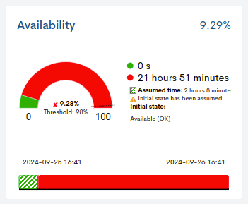
This panel has two graphical elements that provide information related to the availability level of a monitored host in WOCU-Monitoring.
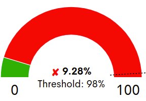
✓ Semicircular graph
Represents the percentage of host availability reached in the last 24 hours. The percentage value is indicated inside the graph, along with the minimum availability Threshold set by the user, marked on the graph with a dashed line.
Depending on whether this threshold is met or not, a green “✓” will appear in front of the availability percentage when the availability exceeds the set value, or a red “X” will appear otherwise.
✓ Time bar
This time bar provides a history of the host’s availability over the last 24 hours, showing the exact moment or period of time when the host was not operational.
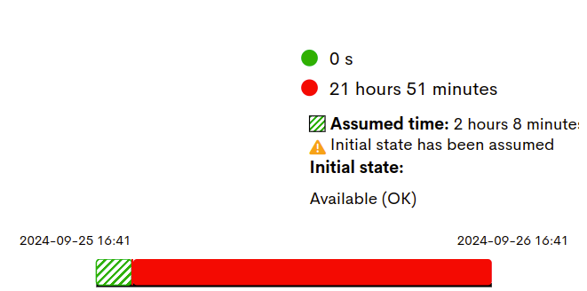
The complementary legend informs about the period of time (in days, hours and seconds) of availability (green colour) and non-availability (red colour) of the host.
There is also the possibility that the system has not collected enough data to determine the initial state of a host. In this case, the user can assume and assign a starting status. This new status is also recorded and displayed in the time bar and in the legend:
Initial State: indicates the state defined by the user, for the time period that will be assumed. This value is configured in the User preferences, specifically in the filter Status Initial SLA Host.
Assumed time: indicates the total duration of the assumed event and is represented on the bar with a grated pattern. The user can configure the initial state of the service in User preferences,specifically in the filter Status Initial SLA Service.
Top 5 monitoring Events
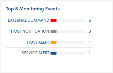
This panel reports, through a maximum of five bars, the most frequent types of Events in the last 24 hours, for the selected host.
Each bar represents a type of event and each one indicates the number of times an event has occurred.
Summary view
By activating the icon marked in the following image, the previous KPIs are displayed, but in a more compact format for quick reading:

It is also possible to hide the panel block by togglingboth buttons.

Health
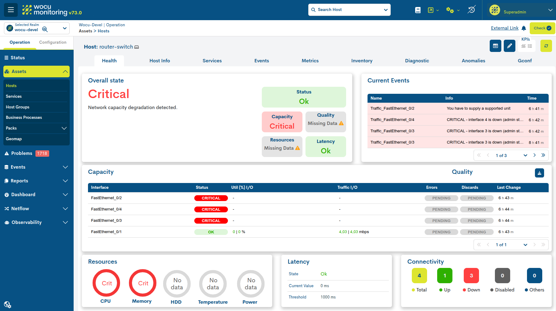
The Health view provides a consolidated graphical representation of the operational status of network devices monitored in WOCU Monitoring.Its objective is to offer a quick and accurate assessment of a device’s health based on multiple performance indicators, availability, and capacity, allowing the detection of degradation, saturation, or potential failure before they affect service availability.
Therefore, this view is designed to quickly answer questions such as:
Is the device functioning correctly?
Does it show symptoms of degradation or overload?
Are there any components exhibiting anomalous behavior?
Is a review or intervention necessary?
Compatible devices
This functionality is currently available for the following technologies:technologies:
Technology |
Description |
The view provides information about: |
|---|---|---|
Routers |
Device responsible for routing traffic between different networks. |
|
Switches |
Device responsible for switching traffic within a local network.local |
|
Firewalls |
Security device responsible for filtering and controlling traffic. |
|
Access Points (AP) |
Centralized platform for the management of wireless infrastructures. |
|
Requirements
The Health view combines information from various metricscollected by the monitoring packages associated with the device,providing a more complete view of the actual behavior of the device.
For health indicators to be calculated correctly, it is necessary that the device has the packages corresponding to its technology configured and functioning.
Note
If the required packs are not configured or do not generate data, some widgets may appear in a No Data state or not be displayed in the view.
Router and Switch
A device will be identified as a Router or Switch when it has the necessary packages to collect performance metrics and interfaces.
Interface Metrics
To obtain traffic, error, and interface drop information, the device must have one of the following sets of packs:
networkdevice-traffic
networkdevice-traffic-health
networkdevice-traffic-1m
networkdevice-traffic-all: This package integrates into a single monitoring system interface traffic metrics, errors, and dropouts.
networkdevice-traffic-all-1m: This pack integrates into a single monitoring system the traffic metrics, errors, and discards of interfaces.
networkdevice-available-ports: This optional pack allows you to obtain detailed information about the operational status of the ports and device interfaces.
CPU and Memory Metrics
In addition to the interface packs, it is mandatory to have CPU and memory monitoring using one of the following packs:
networkdevice-cpu
networkdevice-cpu-1m
networkdevice-mem
networkdevice-mem-1m
Firewall
A device will be identified as a Firewall when it has any of the following packages applied:
checkpoint-gw-r7720-gaia
checkpoint-mgmt-r7720-gaia
checkpoint-r8010-gaia
fortigate
fortigate-standalone
palo-alto
sourcefire
AP Controller
A device will be identified as an AP Controller when it has applied any of the following packs:
aruba-alcatel-wifi-controller
aruba-alcatel-wifi-iap
cisco-9800-wifi-controller
cisco-wifi-controller
fortigate-wifi-controller
If, on the other hand, a device does not meet the requirements, an information message will appear on the health panel.
Calculating the overall health status of the device
To determine the overall state, the system evaluates the following indicators:indicators:
Status: Device availability.
Capacity: capacity and utilization of monitored resources.
Quality: operational quality of services and interfaces.
Resources: system resource consumption.
Latency: latency behavior and response times.
Each of these indicators can present one of the following states:states:
Status |
Color |
Description |
|---|---|---|
OK |
Green |
The indicator is within expected values. |
Warning |
Yellow |
Conditions have been detected that could lead to a degradation of the service.service. |
Critical |
Red |
There is a significant incidence or deterioration that requires immediate attention.immediate attention. |
General rule of calculation
The global state of health (Health) is obtained by applying a logic of severity on the previous indicators.
The states’ priority is as follows:
Critical > Warning > OK
This means that the existence of an indicator in a critical state will always carry more weight than any other state.
Availability Priority (Status)
The Status indicator has the highest priority within the calculation of the “”global status.
When the device is in a Critical state from the availability point of view, the overall state of the device will automatically be Critical, regardless of the state of the other indicators.
This behavior stems from the fact that an inaccessible or unavailable device is considered a critical incident, even if other indicators show no problems.
Calculation Cases
Case 1: Critical Availability
If the Status indicator is in a Critical state:
Status: Critical
Capacity: any
Quality: any
Resources: any
Latency: any
Health: any
In this scenario, the device is considered non-operational and the overall state will always be critical.
Case 2: There are critical indicators
If the device is available but one or more indicators are in a Critical state:
Status: OK
Capacity: Critical
Quality: OK
Resources: Warning
Latency: OK
Health: Critical
The presence of any critical indicator causes the overall state to be Critical.
Case 3: There are warnings but no critical states
If no indicator is in a Critical state and there is at least one indicator in a Warning state:
Status: OK
Capacity: Warning
Quality: OK
Resources: OK
Latency: Warning
Health: Warning
In this case, the device shows signs of degradation or potential risk, so the overall status will be Warning.
Case 4: All indicators are correct
When all indicators are in the OK state:
Status: OK
Capacity: OK
Quality: OK
Resources: OK
Latency: OK
Health: OK
The device is considered completely healthy and the overall status will be OK.
Interpretation of the result
The status displayed in the widget Overall state should be interpreted as a consolidated assessment of the device and constitutes the main entry point for diagnosis.
When the overall status is Critical or Warning, it is recommended to review the individual widgets to identify which health dimension (availability, capacity, quality, resources, or latency) is causing the degradation and analyze the associated details.
Routers/Switch specific view
The view is organized into different widgets presented and ordered according to their relevance.their relevance.
Overall state
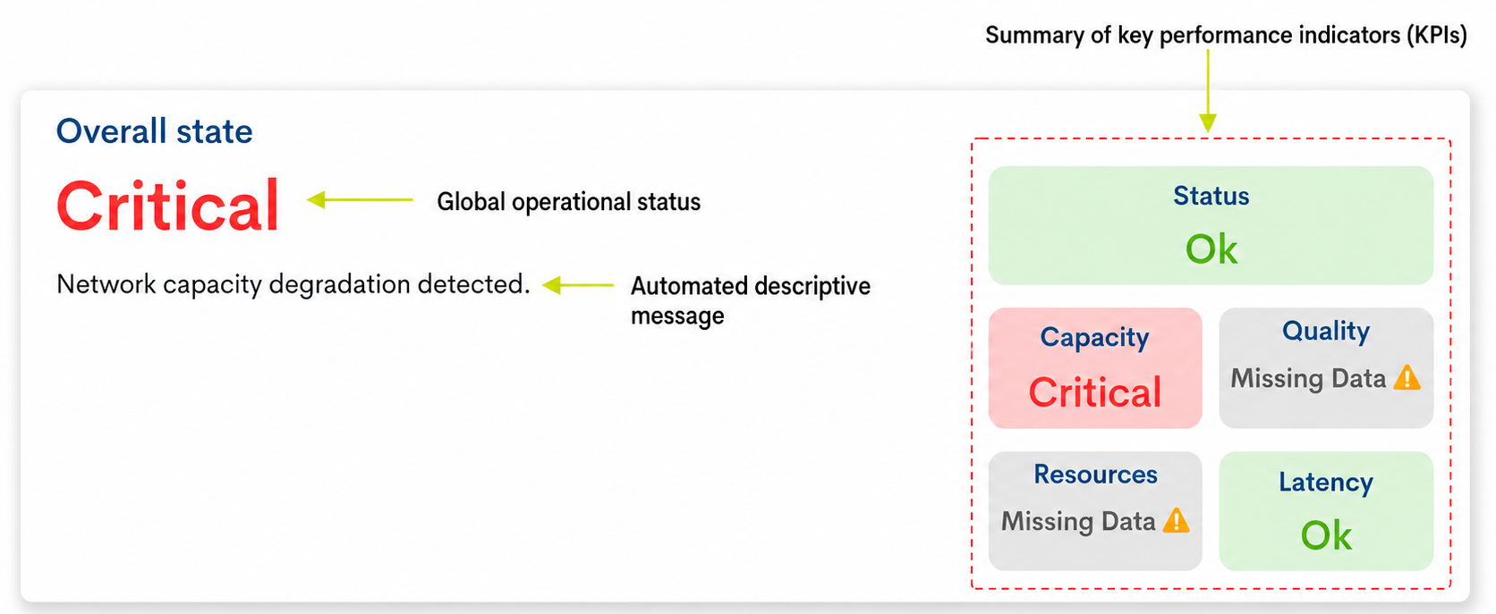
It constitutes the main indicator of the Health view. It is designed as a quick entry point for diagnosis, by consolidating the overall operational status of the device from the other available indicators. Its objective is to offer an initial and unified reference, on the current health of the equipment along with the specific reasons that originate it.
Possible global states:
OK: The device is functioning within expected parameters and no relevant issues are detected.
Critical: one or more indicators are detected in a critical state that require immediate review.
Warning: Conditions have been identified that could affect the performance or stability of the device.
Unknown: There is not enough information to calculate the global state of the device.the device.
Important
The following link explains how to perform the Calculating the overall health status of the device, which is predetermined by the individual state of the other widgets.
This widget not only visually indicates the criticality level of the device, but also includes an automated descriptive message. This message acts as a direct justification, allowing you to identify the root cause or the exact component affecting the device’s health.
The message displayed on the screen corresponds to the specific KPI that triggered the state change, classified according to its level of severity. See the following summary table of possible messages:
Summary of Key Performance Indicators (KPIs)
Displays a summary of the overall status of each of the blocks (KPIs) that determine the overall health of the device.
Example of Rapid Diagnosis
Let’s imagine a network operator accesses the Health view of a main switch and observes the widget Overall state with the following behavior:
The overall indicator is displayed in red with the informational text
Critical.The supplementary message
Network capacity degradation detected.On the right, the
Capacityblock is shown in red, which is the responsible KPI.KPI.
How should it be interpreted?
Thanks to the message, the operator immediately identifies that the root causeof the critical alert is a bandwidth saturation problem orinterfaces.
By locating the specific Capacity widget in the same view, you can see at a glance that the FastEthernet0/1 interface is at the limit of its input/output (I/O) usage, instantly validating the WOCU-Monitoring automatic diagnostic.
Current Events
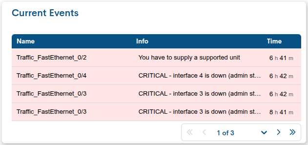
The Current Events widget displays the most recent active events associated with the device, providing immediate information about incidents or status changes that may be affecting its operational health.
Its objective is to complement the overall status, allowing for the rapid identification of events that contribute to a warning or critical situation. Four events are displayed per page.
The following information is displayed for each event:
Name: Name of the device or service associated with the event.
Info: description of the recorded event.
Time: Time elapsed since the event became active.Events are displayed in order of activation date, with the most recent events shown first.
Note
This information is extracted from the global table Events.
States of events
Each row in the table uses a background color to visually identify the severity of the event and facilitate its interpretation.
Green color: corresponds to the OK status. The asset is operational and functioning within the expected parameters.
Yellow color: corresponds to the Warning status. A condition has been detected that requires monitoring, although it does not critically affect the asset’s operation.
Red color: There is an issue that may affect the operation of the device or service and requires immediate attention.
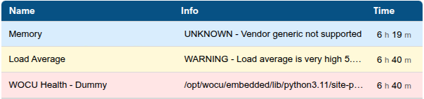
Blue color: corresponds to the Unknown status. It indicates that the status of the asset, service, or metric could not be determined due to missing data, a communication error, or an unsupported check.
Capacity & Quality
This widget is the main component of the Health view for Router and Switch devices. Its purpose is to provide a detailed view of the operational status of the monitored interfaces, allowing for the rapid identification of capacity issues, utilization problems, errors, or service degradation.
Requirements
This widget will only display information from the interfaces that are being monitored. For the data to be available, the device must have the corresponding monitoring packages configured.
More information at: Requirements > Router and Switch.

The table is divided into two functional blocks:
Capacity
Displays information related to the use and capacity of the interfaces.
Important
The interfaces are automatically ordered according to their operational relevance.The order of presentation follows these criteria:
Interface criticality status.
Usage level (% of load).
Date of last status change.
In this way, the interfaces with the greatest potential impact on the service will always appear in the top positions.
The table includes the following columns:
Interface: Displays the name of the monitored interface.
Status: indicates the operational status of the port. This value is obtained from monitoring the port status and allows you to know if the interface is functioning correctly. The possible states are:
UP: The interface is operational.
Down: The interface is currently unavailable.
UNKN: It is not possible to determine the current state.
Utility (%): Shows the percentage of interface utilization relative to its total capacity. The associated status is calculated using the thresholds defined in the monitoring package Networktrafficdevice.
Traffic I/O: represents the volume of incoming and outgoing traffic of the interface. It is displayed in the format:
Input / Output(for example: 12.4 Mbps / 8.1 Mbps). The color displayed reflects the status of the metric according to the configured thresholds.Automatic unit scaling
To facilitate reading, the unit of measurement is automatically adjustedbased on the monitored value.
Current Unit
Automatic change when the value is reached
bps
1000 bps → Kbps
Kbps
1000 Kbps → Mbps
Mbps
1000 Mbps → Gbps
Gbps
1000 Gbps → Tbps
When input and output values are displayed simultaneously, both use the same unit of measurement, determined by the larger of the two values.
Quality
Displays indicators related to the quality of communications.Includes the following columns:
Errors: Indicates the status of errors detected in the interface. The displayed status depends on the thresholds configured in the monitoring package networkdevice-traffic-health. The possible states are:
OK
Warning
Critical
Unknown
Discards: indicates the status of discarded packets in the interface. Its operation is equivalent to the Errors indicator and uses the same evaluation criteria.
A sustained increase in discards may indicate: congestion, buffer saturation, capacity problems, or incorrect configurations.
Last Change: Displays the date and time of the last state change recorded for the interface. This field allows you to know when the last relevant modification to the interface’s behavior occurred and facilitates correlation with events or incidents detected in the system.
Resources
Provides a unified, real-time view of the main performance and health parameters of the monitored asset’s hardware. Enables operators to identify bottlenecks or anomalies in the infrastructure at a glance.
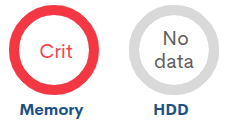
Each resource (CPU, Memory, HDD, Temperature, and Power) is represented by a pie chart that includes the percentage value inside, accompanied by a colored ring that changes according to the status it registers. The status is based on the thresholds previously configured in the monitoring packages.
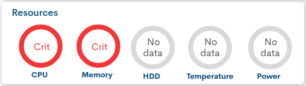
Los estados posibles son:
OK: indicates that the resource is operating within the normal and optimal operating parameters.
Warning: Indicates high usage or abnormal behavior that, while not preventing the asset from functioning, requires preventive attention.
Critical: Indicates a situation of extreme urgency. It requires immediate intervention, as the asset’s performance is severely compromised or at its limit.
Unknown: This state occurs when the system loses the ability to collect or interpret service metrics.
No data: Indicates that no information is available for the resource.This may be because the metric is not monitored, is not supported by the device, or valid data has not yet been received.
Latency
This widget shows the time it takes WOCU-Monitoring to get a response from the monitored device. It’s a basic measure to understand whether the device is accessible and whether communication with it is fast or slow.
Therefore, this indicator is key to evaluating the quality of connectivity, allowing for the proactive detection of routing problems, link saturation, or degradation in data transport.
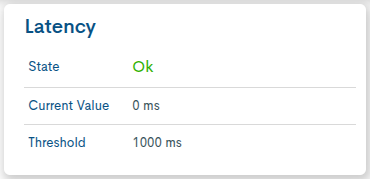
The main components are:
State: Indicates the current latency health status using a color code. The status is based on the thresholds previously configured in the monitoring packs. The possible states are:
OK: Latency is within the threshold defined as normal, indicating that the device responds correctly and no relevant slowness in communication is observed.
Warning: The warning threshold has been exceeded, but the critical level has not yet been reached. The device is still responding, but communication may be degrading.
Critical: The configured critical threshold has been exceeded. The response time is too long and may affect service.
Unknown: This is logged when the system cannot correctly determine the latency status.
Current Value: indicates the actual response time measured in milliseconds (ms) on the last sample.
Threshold: Reflects the maximum allowed limit configured for the device (measured in ms) before the service changes to an alert state.
Connectivity
This widget displays a summary of the status of the physical ports of the monitored device.monitored device.
Its objective is to allow the user to quickly know how many physical interfaces the equipment has and what their status is. It is not designed to measure traffic, errors, or capacity usage, but rather to identify whether the ports are active, down, disabled, or in an unclassified state.
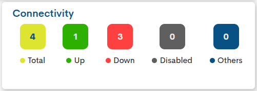
Each counter is interactive and functions as a button. Clicking on one will display a modal window listing the physical ports belonging to that state.
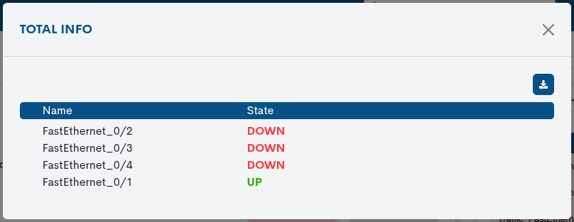
The available options are:
Clicking on Up will display the list of active physical ports.
Clicking Down will display the downed physical ports.
Clicking on Disabled will display the disabled ports.
Clicking on Others will display ports that have a different or unrecognized status.
Within that modal window, the user will also be able to export the data from the list in CSV or JSON format.
Specific Firewall View
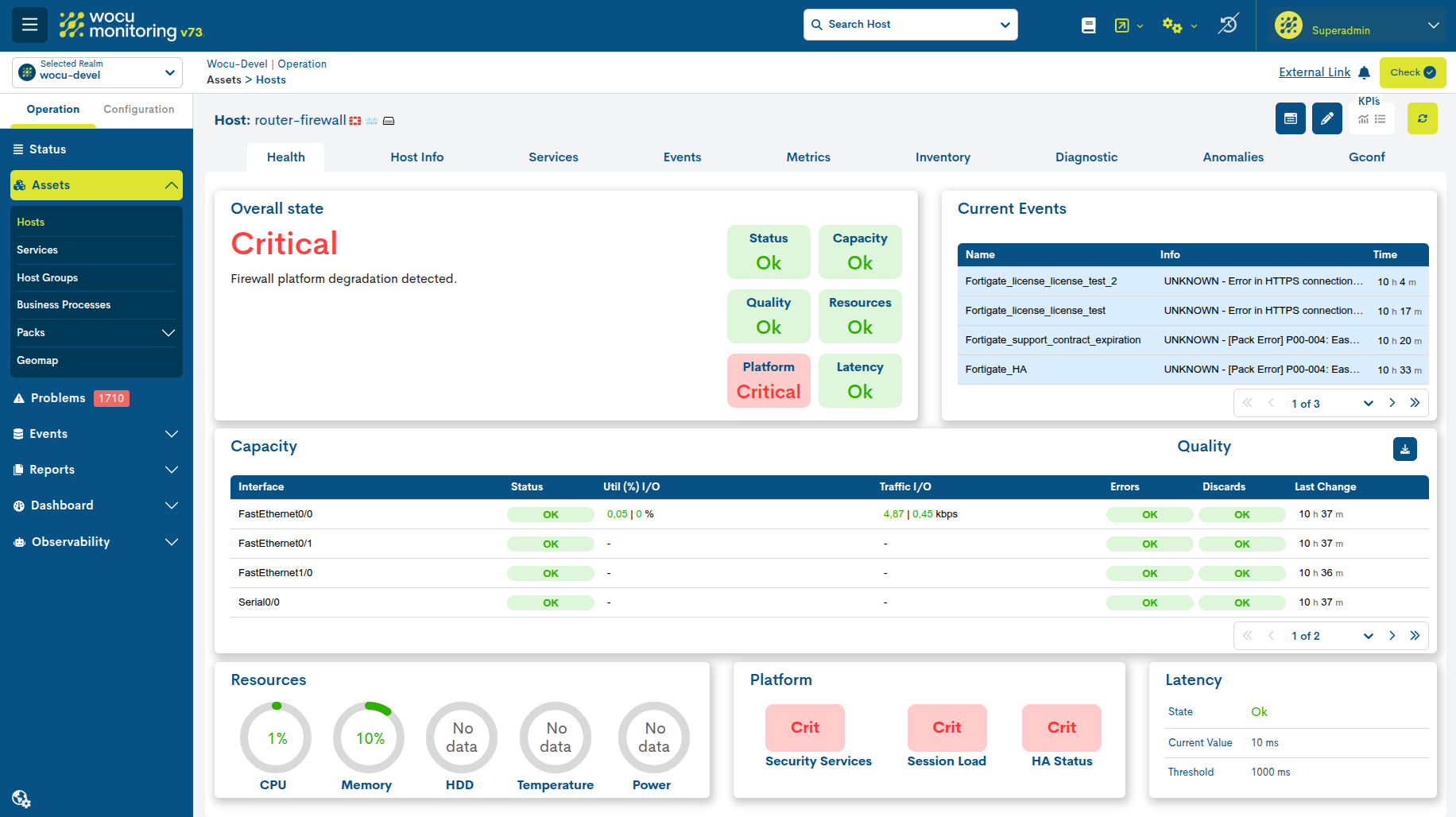
The view is organized into different widgets presented and ordered according to their relevance.their relevance.
Overall state
It constitutes the main indicator of the Health view. It is designed as a quick entry point for diagnosis, by consolidating the overall operational status of the device from the other available indicators. Its objective is to offer an initial and unified reference, on the current health of the equipment along with the specific reasons that originate it.
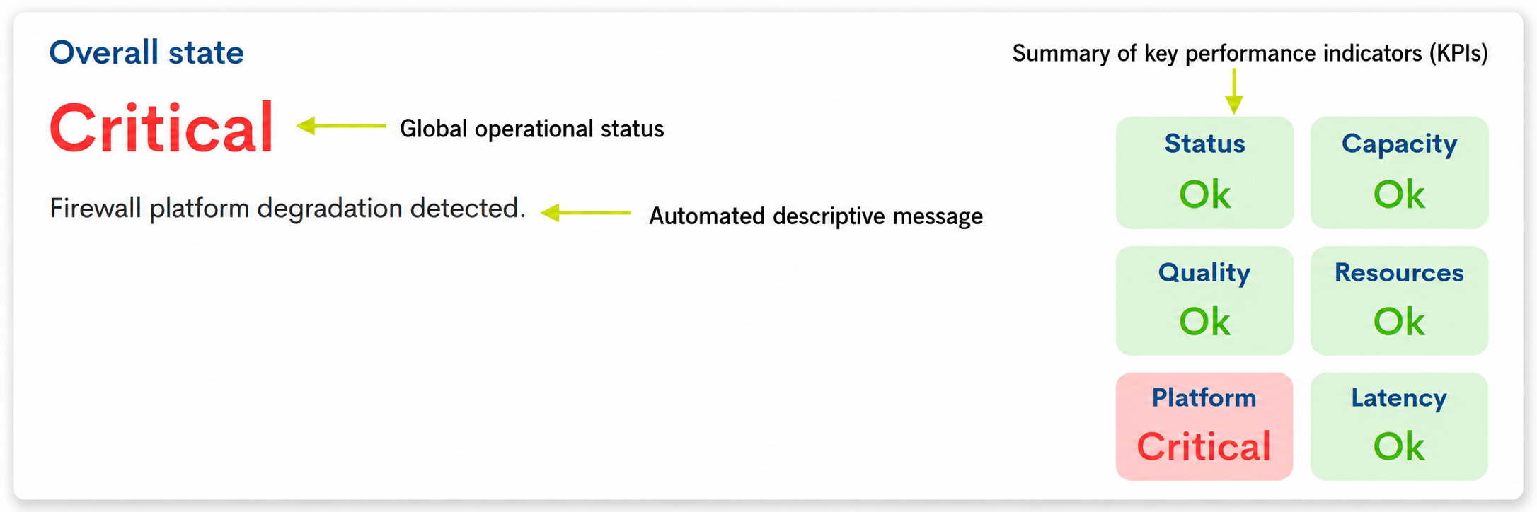
Possible global states:
OK: The device is functioning within expected parameters and no relevant issues are detected.
Critical: one or more indicators are detected in a critical state that require immediate review.
Warning: Conditions have been identified that could affect the performance or stability of the device.
Unknown: There is not enough information to calculate the global state of the device.the device.
Important
The following link explains how to perform the Calculating the overall health status of the device, which is predetermined by the individual state of the other widgets.
This widget not only visually indicates the criticality level of the device, but also includes an automated descriptive message. This message acts as a direct justification, allowing you to identify the root cause or the exact component affecting the device’s health.
The message displayed on the screen corresponds to the specific KPI that triggered the state change, classified according to its level of severity. See the following summary table of possible messages:
Summary of Key Performance Indicators (KPIs)
Displays a summary of the overall status of each of the blocks (KPIs) that determine the overall health of the device.
Current Events
The Current Events widget displays the most recent active events associated with the device, providing immediate information about incidents or status changes that may be affecting its operational health.
Its objective is to complement the overall status, allowing for the rapid identification of events that contribute to a warning or critical situation. Four events are displayed per page.
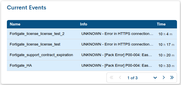
The following information is displayed for each event:
Name: Name of the device or service associated with the event.
Info: description of the recorded event.
Time: Time elapsed since the event became active.Events are displayed in order of activation date, with the most recent events shown first.
Note
This information is extracted from the global table Events.
States of events
Each row in the table uses a background color to visually identify the severity of the event and facilitate its interpretation.
Green color: corresponds to the OK status. The asset is operational and functioning within the expected parameters.
Yellow color: corresponds to the Warning status. A condition has been detected that requires monitoring, although it does not critically affect the asset’s operation.
Red color: There is an issue that may affect the operation of the device or service and requires immediate attention.
Blue color: corresponds to the Unknown status. It indicates that the status of the asset, service, or metric could not be determined due to missing data, a communication error, or an unsupported check.
Capacity & Quality
This widget is the main component of the Health view for Firewall devices. Its purpose is to provide a detailed view of the operational status of the monitored interfaces, allowing for the rapid identification of capacity issues, utilization problems, errors, or service degradation.
Requirements
This widget will only display information from the interfaces that are being monitored. For the data to be available, the device must have the corresponding monitoring packages configured.
More information at: Requirements > Router and Switch.

The table is divided into two functional blocks:
Capacity
Displays information related to the use and capacity of the interfaces.
Important
The interfaces are automatically ordered according to their operational relevance.The order of presentation follows these criteria:
Interface criticality status.
Usage level (% of load).
Date of last status change.
In this way, the interfaces with the greatest potential impact on the service will always appear in the top positions.
The table includes the following columns:
Interface: Displays the name of the monitored interface.
Status: indicates the operational status of the port. This value is obtained from monitoring the port status and allows you to know if the interface is functioning correctly. The possible states are:
UP: The interface is operational.
Down: The interface is currently unavailable.
UNKN: It is not possible to determine the current state.
Utility (%): Shows the percentage of interface utilization relative to its total capacity. The associated status is calculated using the thresholds defined in the monitoring package Networktrafficdevice.
Traffic I/O: represents the volume of incoming and outgoing traffic of the interface. It is displayed in the format:
Input / Output(for example: 12.4 Mbps / 8.1 Mbps). The color displayed reflects the status of the metric according to the configured thresholds.Automatic unit scaling
To facilitate reading, the unit of measurement is automatically adjustedbased on the monitored value.
Current Unit
Automatic change when the value is reached
bps
1000 bps → Kbps
Kbps
1000 Kbps → Mbps
Mbps
1000 Mbps → Gbps
Gbps
1000 Gbps → Tbps
When input and output values are displayed simultaneously, both use the same unit of measurement, determined by the larger of the two values.
Quality
Displays indicators related to the quality of communications.Includes the following columns:
Errors: Indicates the status of errors detected in the interface. The displayed status depends on the thresholds configured in the monitoring package networkdevice-traffic-health. The possible states are:
OK
Warning
Critical
Unknown
Discards: indicates the status of discarded packets in the interface. Its operation is equivalent to the Errors indicator and uses the same evaluation criteria.
A sustained increase in discards may indicate: congestion, buffer saturation, capacity problems, or incorrect configurations.
Last Change: Displays the date and time of the last state change recorded for the interface. This field allows you to know when the last relevant modification to the interface’s behavior occurred and facilitates correlation with events or incidents detected in the system.
Resources
Provides a unified, real-time view of the main performance and health parameters of the monitored asset’s hardware. Enables operators to identify bottlenecks or anomalies in the infrastructure at a glance.
Each resource (CPU, Memory, HDD, Temperature, and Power) is represented by a pie chart that includes the percentage value inside, accompanied by a colored ring that changes according to the status it registers. The status is based on the thresholds previously configured in the monitoring packages.
Los estados posibles son:
OK: indicates that the resource is operating within the normal and optimal operating parameters.
Warning: Indicates high usage or abnormal behavior that, while not preventing the asset from functioning, requires preventive attention.
Critical: Indicates a situation of extreme urgency. It requires immediate intervention, as the asset’s performance is severely compromised or at its limit.
Unknown: This state occurs when the system loses the ability to collect or interpret service metrics.
No data: Indicates that no information is available for the resource.This may be because the metric is not monitored, is not supported by the device, or valid data has not yet been received.
Platform
This block summarizes the status of the firewall’s functional components,such as licenses, session load, and high availability.
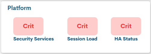
The indicators included are:
Security Services: Displays the most critical status associated with the firewall’s security services and licenses.
Clicking this button opens the Licenses Info modal window, which displays details of the licenses and security services associated with the firewall. From this window, you can view the name of each license, its status, and related technical information. The status of the Security Services indicator is calculated based on the worst status detected among the listed licenses, so any license in a Critical status will cause the block to be displayed as critical.
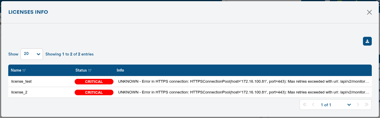
Session Load: Indicates the level of session or connection load managed by the firewall. It allows you to detect situations where the session volume may be approaching the device’s capacity limits.
HA Status: Displays the high availability status of the firewall, when this functionality is configured or available. This indicator allows you to check if the node or cluster is in a correct state. If not applicable, it can be displayed as N/A.
The displayed status always corresponds to the most critical condition detected among its indicators, allowing the operator to quickly identify problems that may affect the overall operation of the platform. The following order of priority is followed:
Critical > Warning > Unknown > OK
For example, if Security Services is in OK state, but Session Load or HA Status is in Critical state, the Platform block will be displayed as Critical, since there is a condition that requires immediate attention.
Latency
This widget shows the time it takes WOCU-Monitoring to get a response from the monitored device. It’s a basic measure to understand whether the device is accessible and whether communication with it is fast or slow.
Therefore, this indicator is key to evaluating the quality of connectivity, allowing for the proactive detection of routing problems, link saturation, or degradation in data transport.
The main components are:
State: Indicates the current latency health status using a color code. The status is based on the thresholds previously configured in the monitoring packs. The possible states are:
OK: Latency is within the threshold defined as normal, indicating that the device responds correctly and no relevant slowness in communication is observed.
Warning: The warning threshold has been exceeded, but the critical level has not yet been reached. The device is still responding, but communication may be degrading.
Critical: The configured critical threshold has been exceeded. The response time is too long and may affect service.
Unknown: This is logged when the system cannot correctly determine the latency status.
Current Value: indicates the actual response time measured in milliseconds (ms) on the last sample.
Threshold: Reflects the maximum allowed limit configured for the device (measured in ms) before the service changes to an alert state.
AP specific view
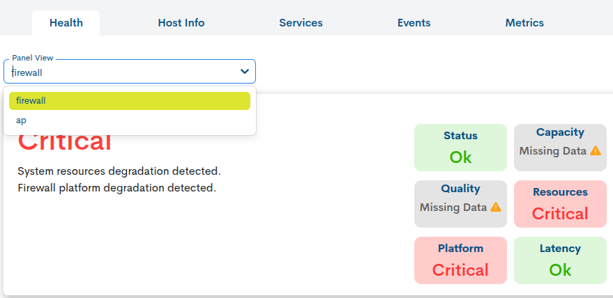
When a single asset has several associated packs and can belong to more than one type, for example Firewall and AP, the Health view incorporates a view selector.
This selector allows you to switch between the different views available for the asset and consult the specific indicators for each one. In this way, the user can analyze the same device from different operational perspectives without leaving the detailed view.
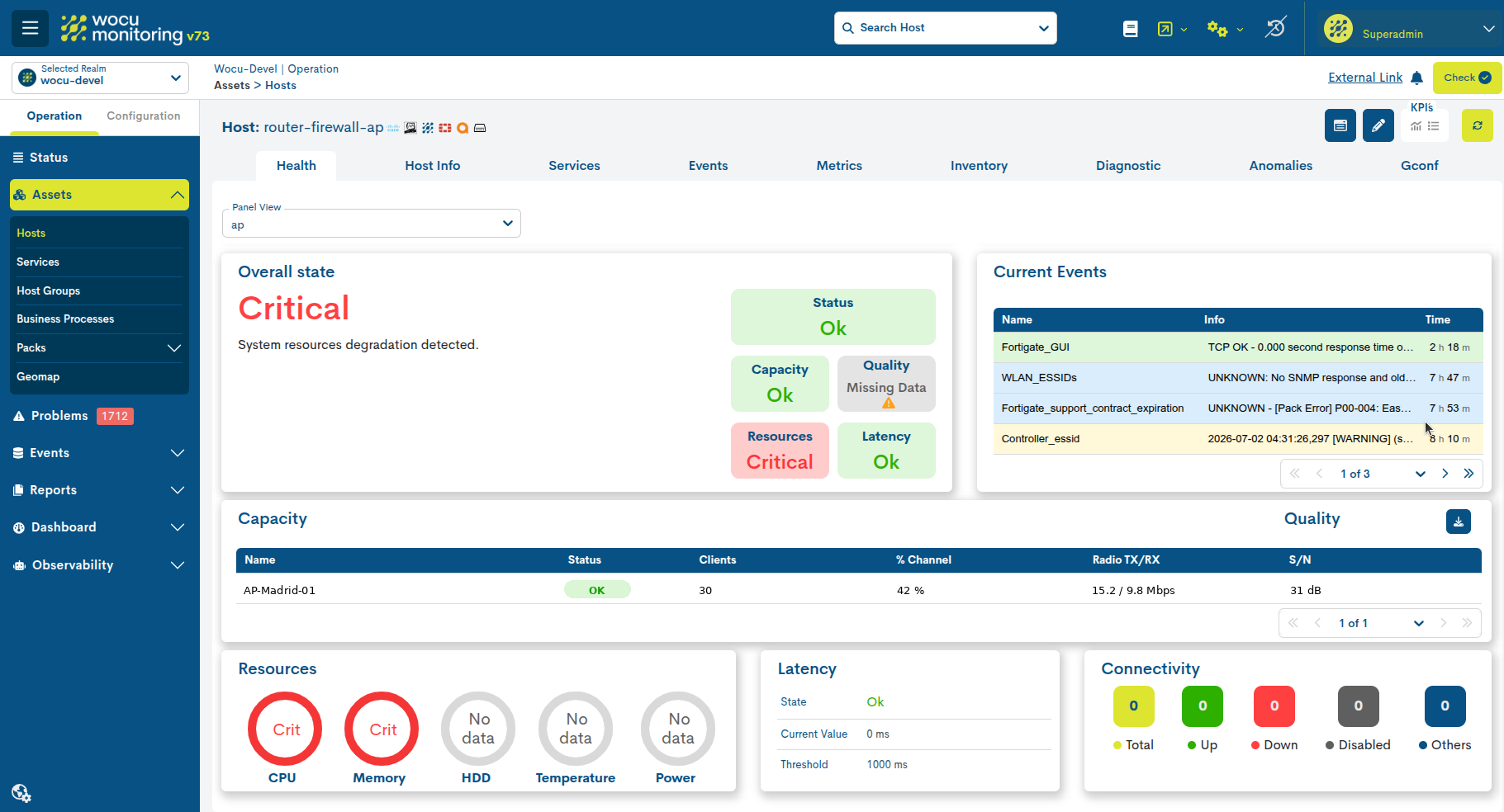
The view is organized into different widgets presented and ordered according to their relevance.their relevance.
Overall state
It constitutes the main indicator of the Health view. It is designed as a quick entry point for diagnosis, by consolidating the overall operational status of the device from the other available indicators. Its objective is to offer an initial and unified reference, on the current health of the equipment along with the specific reasons that originate it.
Possible global states:
OK: The device is functioning within expected parameters and no relevant issues are detected.
Critical: one or more indicators are detected in a critical state that require immediate review.
Warning: Conditions have been identified that could affect the performance or stability of the device.
Unknown: There is not enough information to calculate the global state of the device.the device.
Important
The following link explains how to perform the Calculating the overall health status of the device, which is predetermined by the individual state of the other widgets.
This widget not only visually indicates the criticality level of the device, but also includes an automated descriptive message. This message acts as a direct justification, allowing you to identify the root cause or the exact component affecting the device’s health.
The message displayed on the screen corresponds to the specific KPI that triggered the state change, classified according to its level of severity. See the following summary table of possible messages:
Current Events
The Current Events widget displays the most recent active events associated with the device, providing immediate information about incidents or status changes that may be affecting its operational health.
Its objective is to complement the overall status, allowing for the rapid identification of events that contribute to a warning or critical situation. Four events are displayed per page.
The following information is displayed for each event:
Name: Name of the device or service associated with the event.
Info: description of the recorded event.
Time: Time elapsed since the event became active.Events are displayed in order of activation date, with the most recent events shown first.
Note
This information is extracted from the global table Events.
States of events
Each row in the table uses a background color to visually identify the severity of the event and facilitate its interpretation.
Green color: corresponds to the OK status. The asset is operational and functioning within the expected parameters.
Yellow color: corresponds to the Warning status. A condition has been detected that requires monitoring, although it does not critically affect the asset’s operation.
Red color: There is an issue that may affect the operation of the device or service and requires immediate attention.
Blue color: corresponds to the Unknown status. It indicates that the status of the asset, service, or metric could not be determined due to missing data, a communication error, or an unsupported check.
Capacity & Quality
This widget gathers the main indicators associated with the monitored access points. Each row represents an AP and displays its status along with relevant metrics to assess its load and performance.
The available columns are:

The available columns are:
Name: Displays the name of the monitored AP.
Status: Indicates the operational status of the AP using a visual label. Uses the same general states as the other views: OK, Warning, Critical, and Unknown.
Clients: Shows the number of clients connected to the AP. The value is evaluated according to the configured thresholds, allowing the identification of access points with a high user load.
% Channel: Indicates the percentage of wireless channel usage. A high value may reflect saturation of the radio medium or a possible degradation of WiFi performance.
Radio TX/RX: Displays the AP’s transmit and receive traffic. Its behavior is equivalent to the Traffic I/O indicator used in other asset types.
S/N: Displays the signal-to-noise ratio of the access point. This value allows you to evaluate the quality of the wireless signal relative to the detected noise. It is displayed along with its status according to the configured thresholds.
Resources
Provides a unified, real-time view of the main performance and health parameters of the monitored asset’s hardware. Enables operators to identify bottlenecks or anomalies in the infrastructure at a glance.
Each resource (CPU, Memory, HDD, Temperature, and Power) is represented by a pie chart that includes the percentage value inside, accompanied by a colored ring that changes according to the status it registers. The status is based on the thresholds previously configured in the monitoring packages.
Los estados posibles son:
OK: indicates that the resource is operating within the normal and optimal operating parameters.
Warning: Indicates high usage or abnormal behavior that, while not preventing the asset from functioning, requires preventive attention.
Critical: Indicates a situation of extreme urgency. It requires immediate intervention, as the asset’s performance is severely compromised or at its limit.
Unknown: This state occurs when the system loses the ability to collect or interpret service metrics.
No data: Indicates that no information is available for the resource.This may be because the metric is not monitored, is not supported by the device, or valid data has not yet been received.
Latency
This widget shows the time it takes WOCU-Monitoring to get a response from the monitored device. It’s a basic measure to understand whether the device is accessible and whether communication with it is fast or slow.
Therefore, this indicator is key to evaluating the quality of connectivity, allowing for the proactive detection of routing problems, link saturation, or degradation in data transport.
The main components are:
State: Indicates the current latency health status using a color code. The status is based on the thresholds previously configured in the monitoring packs. The possible states are:
OK: Latency is within the threshold defined as normal, indicating that the device responds correctly and no relevant slowness in communication is observed.
Warning: The warning threshold has been exceeded, but the critical level has not yet been reached. The device is still responding, but communication may be degrading.
Critical: The configured critical threshold has been exceeded. The response time is too long and may affect service.
Unknown: This is logged when the system cannot correctly determine the latency status.
Current Value: indicates the actual response time measured in milliseconds (ms) on the last sample.
Threshold: Reflects the maximum allowed limit configured for the device (measured in ms) before the service changes to an alert state.
Connectivity
This widget displays a summary of the status of the physical ports of the monitored device.monitored device.
Its objective is to allow the user to quickly know how many physical interfaces the equipment has and what their status is. It is not designed to measure traffic, errors, or capacity usage, but rather to identify whether the ports are active, down, disabled, or in an unclassified state.
Each counter is interactive and functions as a button. Clicking on one will display a modal window listing the physical ports belonging to that state.
The available options are:
Clicking on Up will display the list of active physical ports.
Clicking Down will display the downed physical ports.
Clicking on Disabled will display the disabled ports.
Clicking on Others will display ports that have a different or unrecognized status.
Within that modal window, the user will also be able to export the data from the list in CSV or JSON format.
Host Info
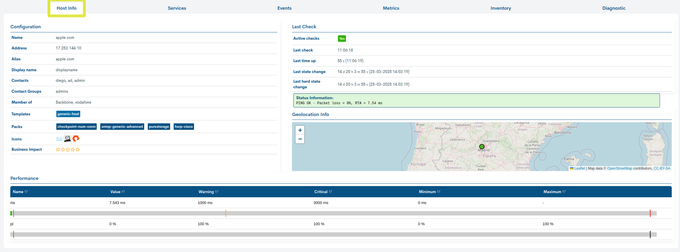
The Host Info tab of this detail view provides detailed information on the configuration, properties, and status of the selected host. The data is displayed across four main panels, explained below.
Configuration
This table displays information about the host and its monitoring configuration, i.e. the basic attributes defined when the host is registered in WOCU-Monitoring.
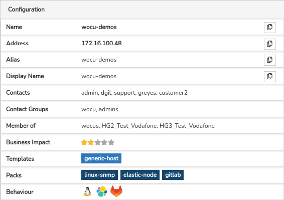
These attributes are as follows:
Name: is the formal name or identifier of the host.
Address: is the Network or IP address of the host.
Alias: is the alternative name of the host.
Display name: this is the name by which the host will be known in WOCU-Monitoring.
Contacts: these are the people in charge of managing the host to be contacted in the event of an incident.
Contact Groups: group of people who are in charge of the management of the host to be contacted in case of an incident on the host.
Member of: when a host belongs to one or several Hostgroups, this information shall be indicated in this field. It may happen that the available space is exceeded, in this case an ellipsis (…) is included to indicate that the text continues but has been cut. However, the list of Host Groups can be consulted by placing the cursor over this text. This field will not be visible when the host is not integrated in any group.
Business Impact: this field marks a value on a scale in scale (from 0 to 5) indicating the importance or significance of the that element. The values are:
None: 0 stars
Low : 1 star
Medium: 2 stars
High: 3 stars
Very High: 4 stars
Critical: 5 stars
Templates: this field contains a series of tags that inform the user of the configuration templates used and assigned to the host. Each of the tags corresponds to a Configuration Template applied.
Packs: this field contains a series of tags that inform the user of the configuration of the monitoring profile assigned to the host. Each of the tags corresponds to a Monitoring Pack applied.
Behaviour: this field contains the complete list of icons identifying technologies, manufacturers, usage patterns, etc., that are associated to Monitoring Packs. Remember that the system displays a maximum of three icons in the main header of the modal. Placing the cursor over a particular icon will pop up a text alluding to the entity represented.
Last Check
This table displays information related to the monitoring checks performed by WOCU-Monitoring to assess the operational status of the host.
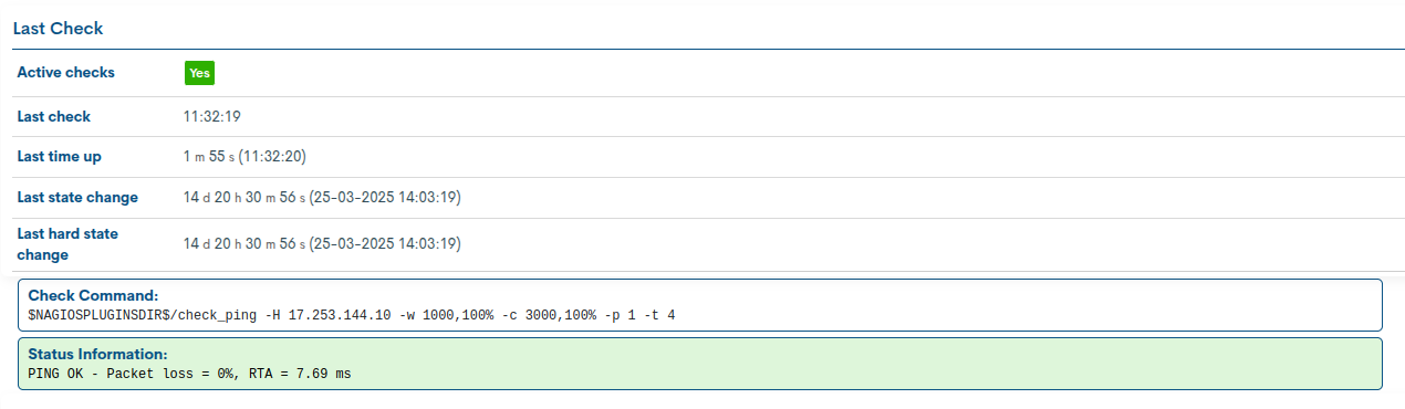
Active Checks: indicates whether the checks option is activated or disabled (Yes or No).
Last Check: informa de la fecha de la última comprobación del Estado del Dispositivo.
Last time up: indicates the exact time at which the host’s status was last UP.
Last state change: indicates the exact time when the monitored host last changed state.
Last hard state change: indicates the exact moment of the last confirmed hard state change. This is an internal concept handled by WOCU-Monitoring and other monitoring systems: transition from a soft state to a hard state. A confirmed hard state change implies confirmation of the deterioration or loss of availability of a host.
Check Command: contains the operation performed internally by WOCU-Monitoring to determine the status of the host. Logically, the value of this field will vary depending on the type of host and its technical characteristics.
Status information: output message obtained with information relating to the current status of the host. The nature of the messages will vary depending on the type of host and its configuration.
Geolocation Info
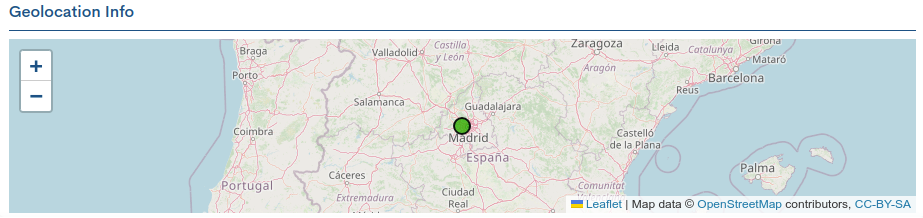
This space shows a map with the exact geographic location of the host in question.
The map will be visible as long as the geographic coordinates of the Host have been included in its configuration.
Performance
In this table, WOCU-Monitoring collects the monitoring metrics generated after the checks that the service launches on the device it depends on. Each metric records performance and capacity values, allowing a deeper analysis of the service, and consequently, of the device in terms of availability.

Note
For more information, the user is referred to the section Performance.
Tickets
In this table, WOCU-Monitoring collects the incident tickets manually registered by the user through the action Add ticket to Host.
The Tickets table shows the following information:
Ticket Number: Displays the identifier linked to the incident (the External ID previously entered).
Type: Technical classification of the problem (the Type previously entered).previously).
Origin: Indicates the source of the incident. In this case, Manual confirms that it was reported directly by a user in WOCU-Monitoring.
Author: Displays the user or the name of the person responsible who registered the incident.the incident.
Message: Summary of the detected problem. Provides the necessary technical context to understand the criticality of the event.
Created at: Exact date and time (with second precision) at which the incident was recorded, allowing calculation of the duration of the failure.
Services
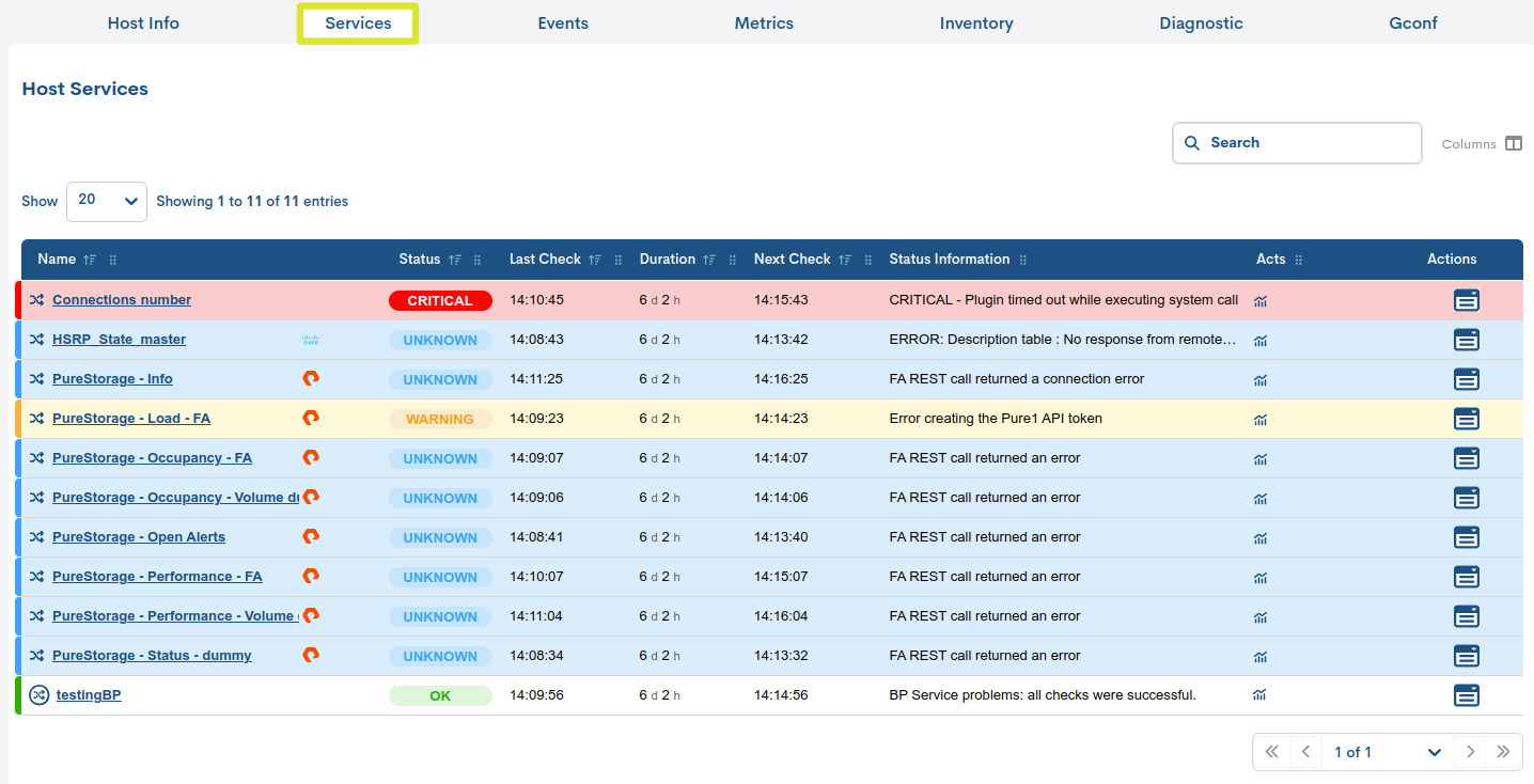
Through this tab, WOCU-Monitoring lists the Services associated with the selected host, and the monitoring status recorded by each of them.
Important
Therefore, the fields shown are virtually the same, except:
Actions field: not present in this Detail View.
Actions field: not present in this Detail View.
Next Check field: present in this Detail View and not in the Assets tab.
Actions field: not present in this Detail View.
Important
The different navigation, search, and sorting options available on this screen are explained in detail in the section: Common navigation, filtering and sorting options.
Events
All event messages produced for the selected host are displayed. These are separated into two sections:
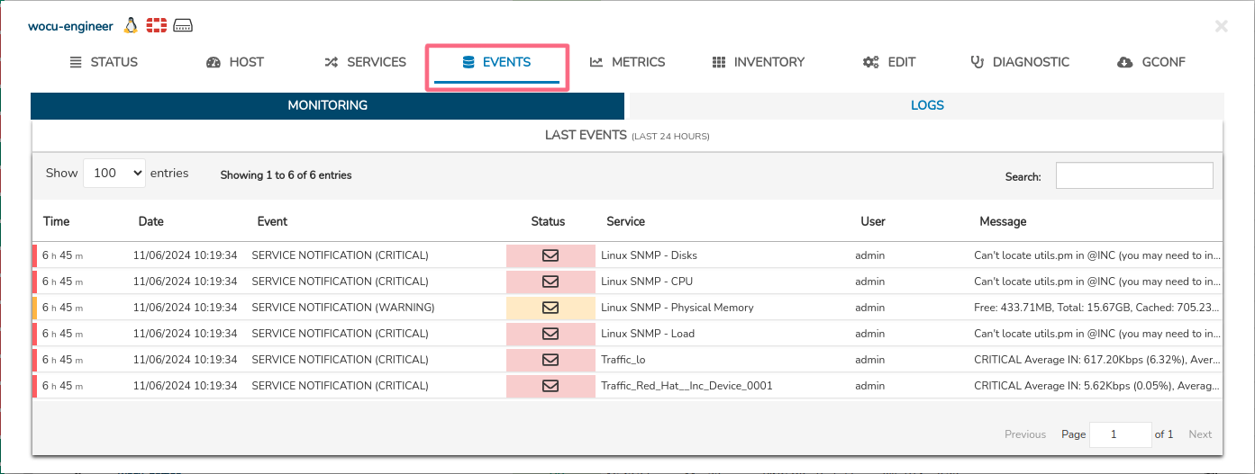
List of Monitoring Events
This section displays the monitoring events of a host that occurred in WOCU-Monitoring in the last 24 hours.
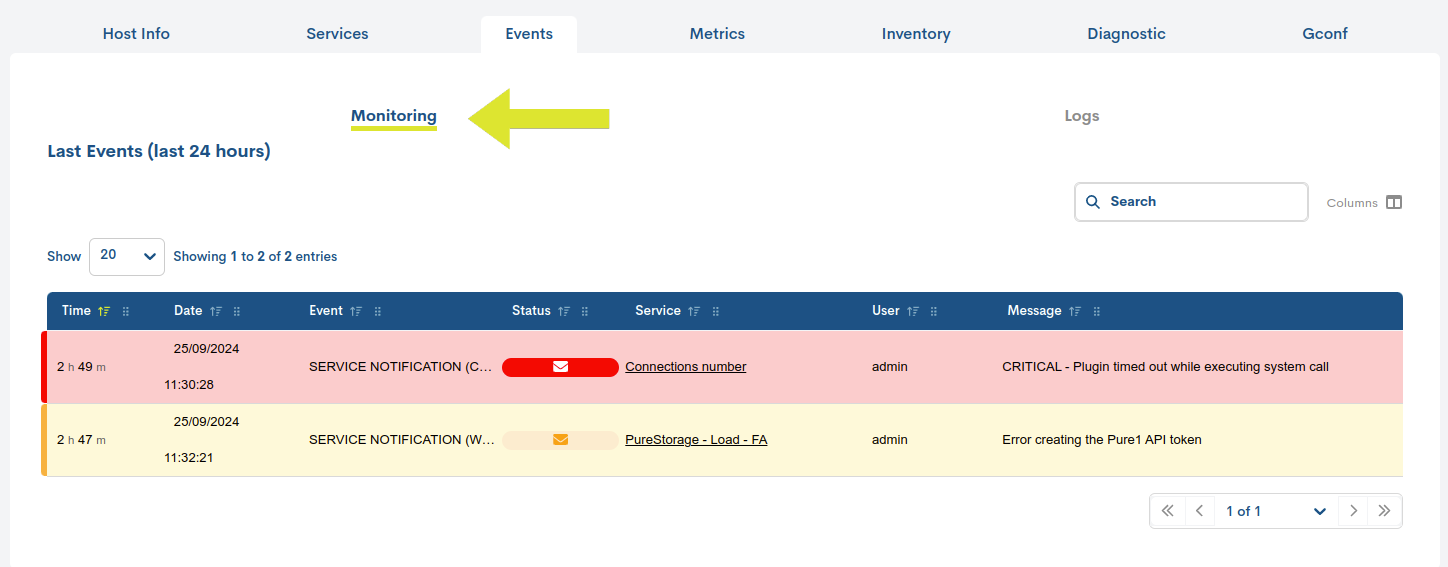
Important
This listing provides the user with information similar to that provided in the Events section for a given realm. Therefore, the fields available in this table are explained in detail in Monitoring Event List Fields.
Other Log Events (Logs)
This section displays other external event messages (independent of WOCU-Monitoring events) but which may be useful in monitoring tasks. That is, all logs generated in the last 24 hours are displayed.
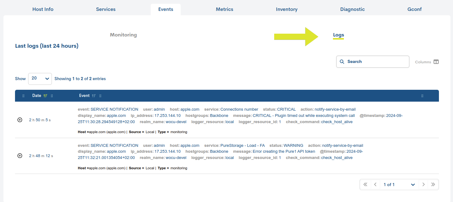
Important
This listing provides the user with information similar to that provided in the Events section for a given realm. Therefore, the fields available in this table are explained in detail in Log Event List Fields.
Metrics
This view provides accurate information on the evolution of the selected host, using performance values collected by WOCU-Monitoring and stored in metrics during a checkup.
They are visualized using graphs that show data collected over specific time periods, as well as indicating defined thresholds for Warning and Critical states.
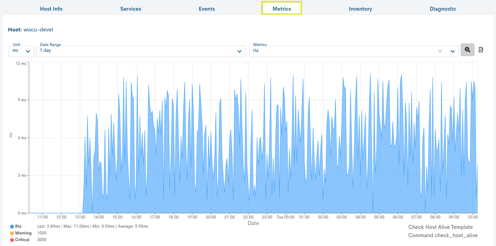
The graph is interactive and allows the following actions:
Interval selection of a metric in the graph itself
Through the Unit selector, it is possible to choose the unit of measurement we want to apply to the graph. This selector allows choosing among the different units available for the selected metric, such as:
Milliseconds (ms): for metrics related to reponse.
Percentage (%): for metrics related to packet losses.
Bytes (B): for metrics related to data size.
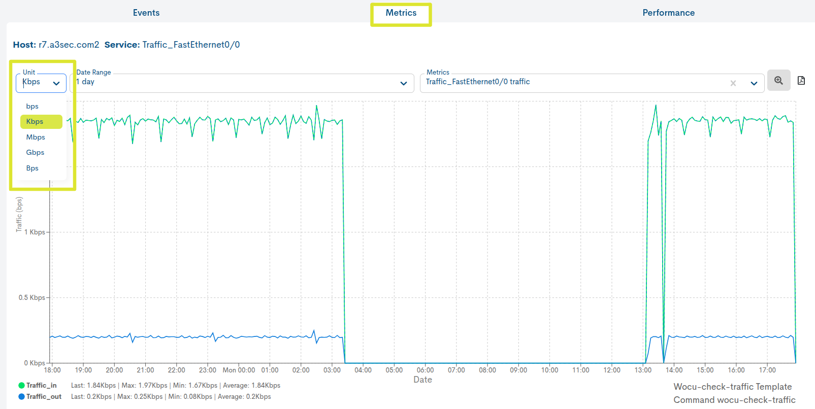
Once the unit is selected, the graph will be automatically updated. to reflect the data in the chosen unit, adjusting the scales and “displayed values. values shown.
Selection of a date range for displaying the data
By default it is set to 1 day, but there are other time criteria to choose from, such as: 4 hours, 1 week, 1 month, 1 year and Custom Range.
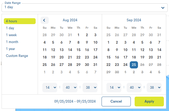
In case you want to set a specific period of time there is the option Custom Range. To configure the time frame it is necessary to set a start date and an end date. By clicking on one of the days, this date will be set as a selection, being marked with a blue background. In addition to the day, a specific time can be set for that day. To do so, use the drop-down menus in the hour, minute and second boxes to set the desired time.
Attention
It is of course not possible to choose start and end dates after the current date, nor to set an end date before the start date.
Selection of the metric whose information is to be displayed
RTA (Round-Trip Average) metric: applied by default. Displays the round-trip times of the Host. The vertical axis scale indicates the unit in which the metric is measured, in this case, milliseconds (ms). The horizontal axis is configured according to the chosen time unit.

PL (Packet loss) metric: shows the percentage of packets lost. The scale on the vertical axis of the graph indicates the unit of measurement, in this case in percentage (%). As in the previous metric, the horizontal axis is configured according to the chosen time unit.

Interval selection of a metric in the graph itself
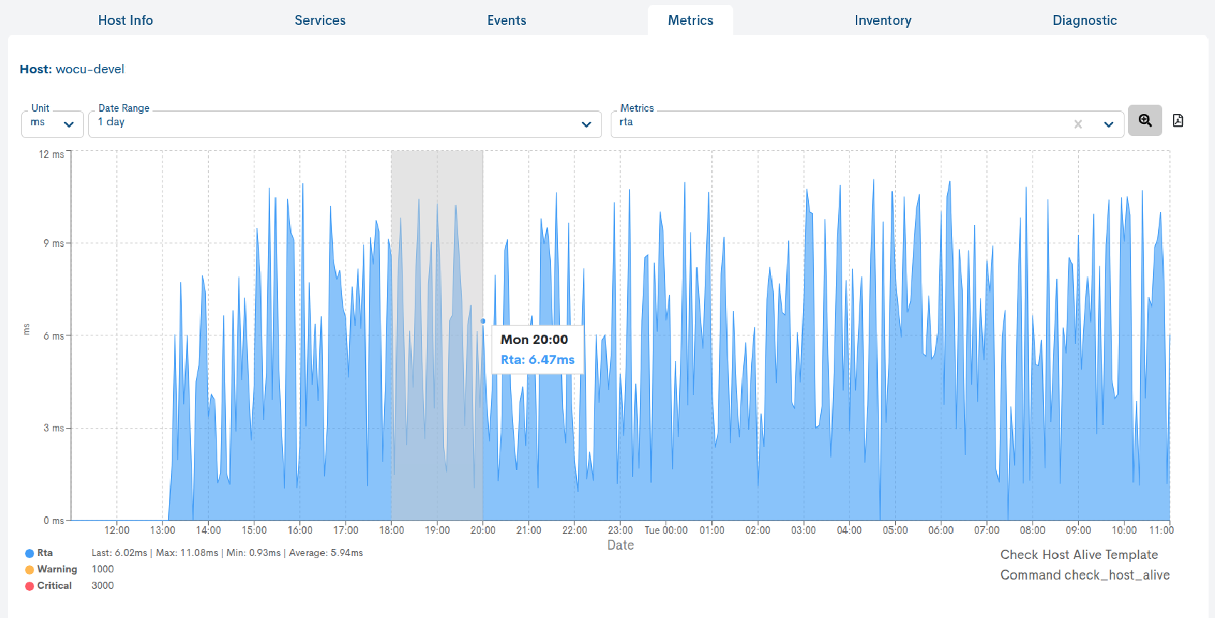
In addition to being able to select (pre-set) time ranges for particular metrics, it is possible to manually select intervals and sub-intervals in the data series and to display a graph of these intervals and sub-intervals.
The selection will be made directly on the graph itself using the mouse. To do this, it is necessary to place the mouse in the area of the generated graph. By clicking and dragging with the left mouse button, a sub-interval within the interval we are visualising will be selected.
Once the range has been selected, we can release the left mouse button, which will result in the graph being updated to show only the defined range.
Note
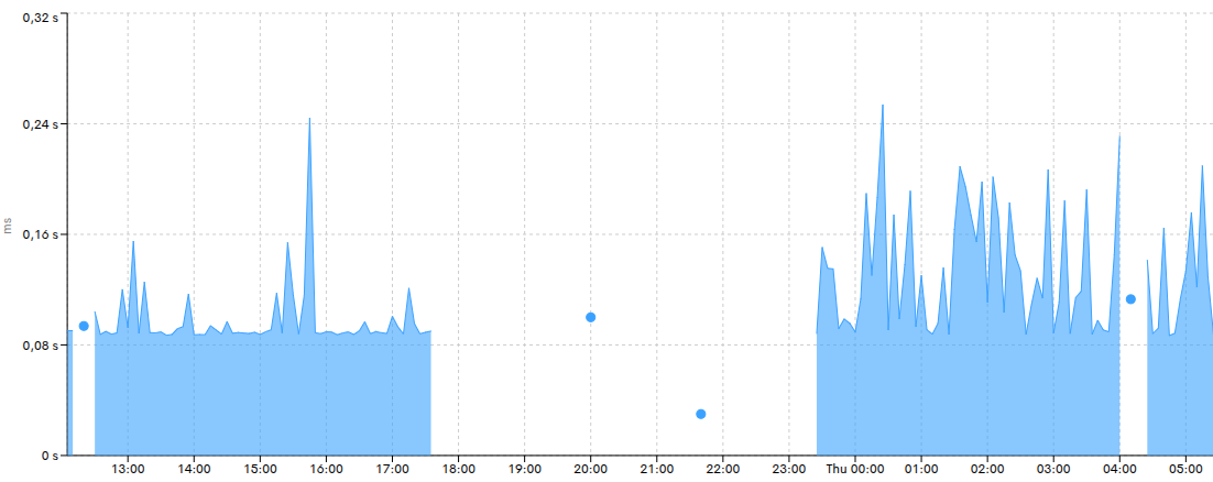
Cuando un valor de una métrica se encuentra precedido y seguido por valores null, este se mostrará mediante un punto visible en la gráfica. De este modo, los valores aislados podrán identificarse directamente sin necesidad de situar el cursor sobre la gráfica para detectarlos.
Esto permite distinguir con mayor claridad los datos puntuales existentes dentro de periodos con ausencia de información.
In addition, in the upper date range bar, the time period corresponding to the manual selection applied shall be specified.

To go back to the initial graph (according to the previously chosen range), the filter has to be re-applied and the displayed data will be restored.
Note
This action can be repeated indefinitely, each time obtaining a smaller selected range than the previous one.
Metrics Forecast
Important
The Forecast button will only be available in those Realms that have the Observability module enabled and use Elasticsearch as their backend technology.
The Pack icons and the selector serve different functions. The selector allows you to navigate between Hosts, while the icons provide visual information about the technology or monitoring profile associated with the selected item.
What is it for?
Forecast is designed to facilitate more proactive monitoring of the monitored resources. Instead of only analyzing what has already happened, it allows you to observe the expected trend of a metric and anticipate possible anomalous behavior or approaches to Warning or Critical levels.
For example, if a CPU utilization metric shows an upward trend, Forecast allows you to visualize how it might evolve over the next few hours and assess whether there is a risk of approaching the configured thresholds. The prediction should be interpreted as an estimate based on observed behavior, and not as an actual value already recorded by the system.
How does it work and how is it used?
Forecast works on the selected time series in the Metrics view of a device. Based on the available historical data, WOCU-Monitoring calculates an estimate of the metric’s future evolution and displays it below the recorded actual values.
To use this feature:
Access the host detail view (by clicking on its host name from any of the application locations where it is located) and then select the Metrics tab.
Select and configure the metric you want to analyze.
Press the Forecast button, identified by the telescope icon and located in the upper right corner of the graph.
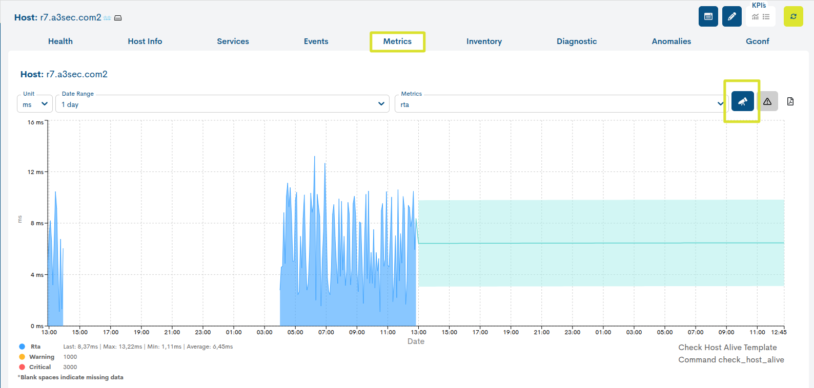
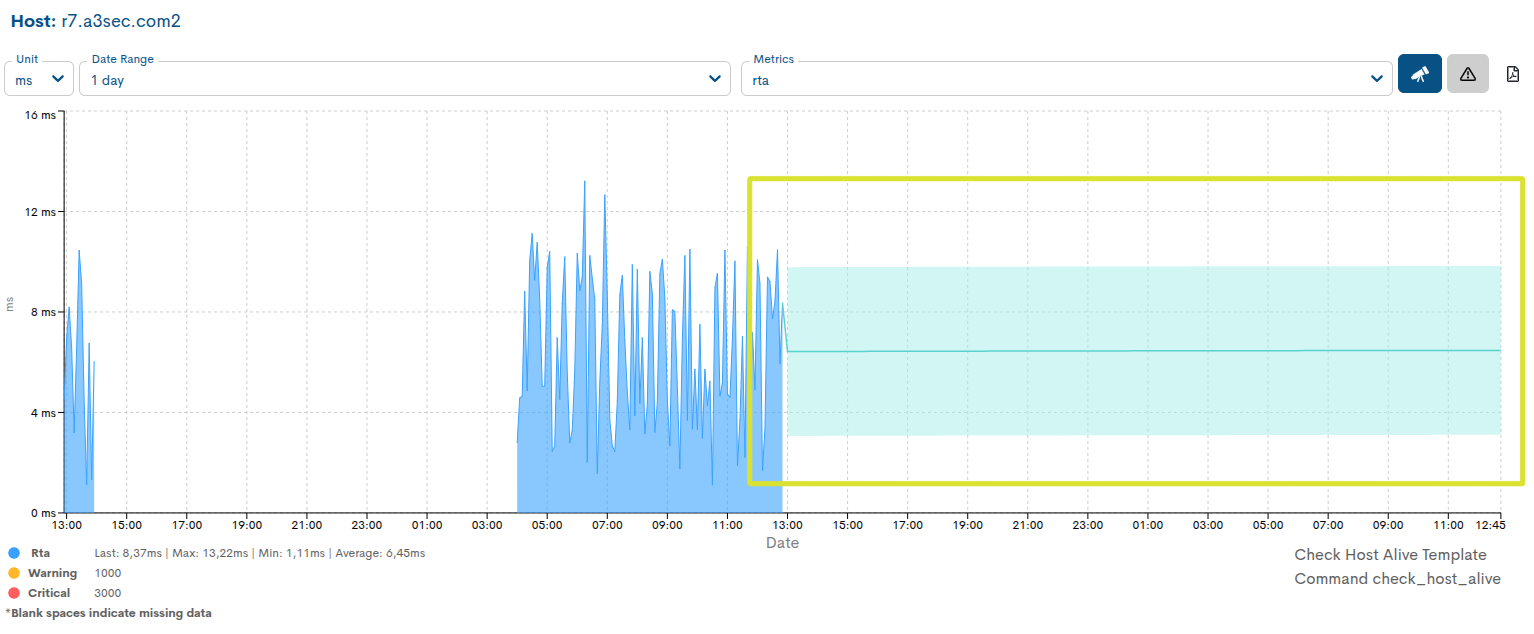
When you activate Forecast, the graph is expanded to incorporate the prediction calculated based on historical data.
Predictive information is represented by a specific Forecast line, allowing it to be visually differentiated from the actual values. This representation is always maintained in line format, regardless of the type of graph selected to display the historical data.
Furthermore, the prediction is accompanied by a shaded area whose purpose is to facilitate its visual identification. This area does not represent a confidence interval or a range of possible values.
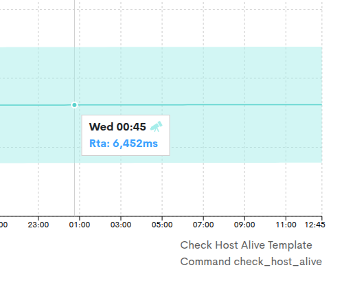
To view the estimated value at a specific moment, place the cursor over the prediction line. The tooltip will display the predicted value for that point in time and will include the identifying color of Forecast and the telescope icon, making it easier to distinguish from the actual measurements collected by WOCU-Monitoring.
Forecast in metrics with multiple series
When a metric contains multiple data series, WOCU-Monitoringallows you to display the Forecast for a single series simultaneously.
For this reason, when a metric contains several series, the legend located in the lower left of the graph allows you to select which one you want to calculate and display the forecast on.
With active Forecast:
The first available series is automatically selected by default.
To change series, press on the corresponding colored circular indicator in the legend.
The selected series will retain its identifying color.
Unselected series will be shown in gray, facilitating the identification of the one on which the prediction is being displayed.
Currently, this interactive series selection is available only while the Forecast functionality is enabled.
Show Critical Reference function
The Show Critical Reference function, available via the button identified with a warning icon, allows you to display on the graph the thresholds configured for state changes of the selected metric.
Activating this option visually represents the references corresponding to:
Warning, identified in yellow.
Critical, identified in red.
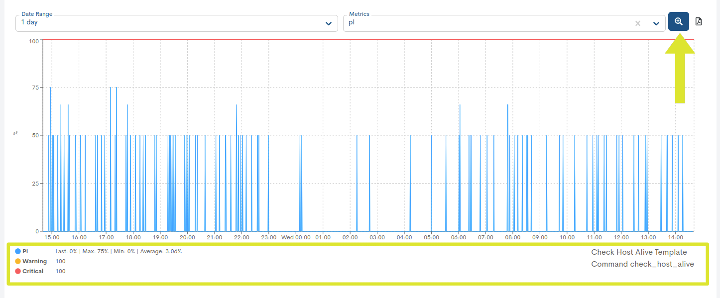
These references, along with the color legend, facilitate the comparison of recorded values with defined thresholds and allow for the rapid identification of when a metric or series reaches warning or criticality levels.
In addition, next to the legend for each metric, reference statistical values are shown, including the last recorded value (last), the maximum value (max), the minimum value (min) and the average value (avg) corresponding to the selected time period.
PDF Export
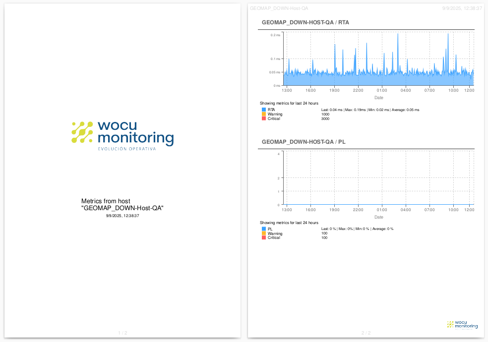
The Export PDF functionality allows you to generate a document in PDF format containing the various graphs based on the metrics displayed in the Metrics view.

This report encapsulates the displayed information, including the selected unit of measurement, the defined time range, and the type of metric queried. This function provides a downloadable, standardized file for further processing or use.
Exporting metrics with Forecast information
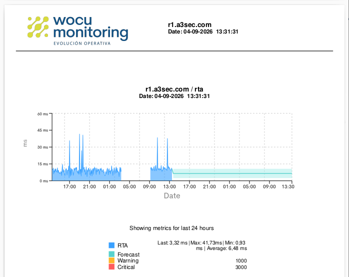
When the Forecast functionality is enabled for the observed metric, the predictive information shown in the graph will also be included in the generated PDF document. This way, the export preserves both the historical data and the estimate of the metric’s future evolution, maintaining the same visual representation available in the interface.
Inventory
This view displays the information collected from the selected device. Devices are registered internally in inventories, where each one is enriched with descriptive data and attributes that characterize its capabilities, configuration, and status.
WOCU-Monitoring features asset enrichment tasks (for example, using SNMP) that automatically collect and update this information. As a result, all the data obtained is consolidated in the Inventory view, providing a centralized point for querying and analyzing the monitored host.
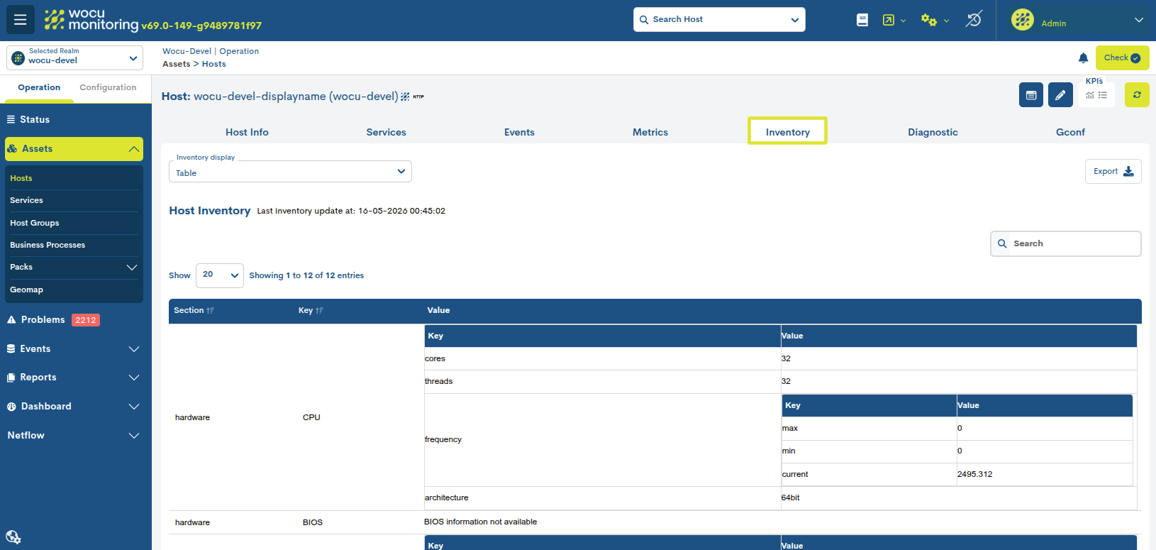
At the top of the table, the date and time of the last device inventory update are displayed, that is, the moment when the device attributes (CPU, memory, disks, etc.) were last collected or updated using the Import Tasks (Tasks).

There are two ways to view inventory data. A through the Inventory Display selector the user can select among the following options:

Table: implemented by default. The data of each of the Devices are registered in a series of fields described belowcontinuation:
Section and Key: Information is segmented into logical categories (e.g., hardware, software, network) and specific keys (e.g., CPU, RAM, OS) for quick component location.
Value: values that a key takes, from a given section. In complex components such as the CPU, the view is broken down into sub-tables that show detailed attributes such as the number of cores, threads, architecture, and operating frequencies.
Important
If the Enable Inventory option is enabled in the device creation and configuration, the inventory collection via SNMP for the new device is automatically initiated through the SNMP_Inventory Task.
It is possible to assign inventories to hosts from the administration interface and through the use of the API.

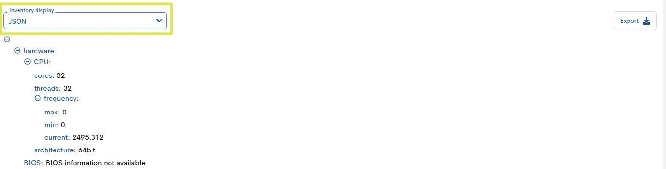
JSON: this view allows you to display the information in a waynested, with the option to expand or collapse all parametersdisplayed in the structure under the user’s choice.
Inventory data export
Although WOCU-Monitoring offers a multitude of functions for the data management, metrics, charts, etc., at some pointmay require the use of other external tools to address suchinformation. To do this, the export function is integrated, which makes it easy to download inventory data in a file to diskhard, for further treatment or use.
Through the Export selector, it is possible to download in “” forma:guilabel:CSV or JSON, the inventory data. In both options, the system will offer the option to select the directorywhere to download and store the generated inventory file and assignan alternative name to it.

BP Trace
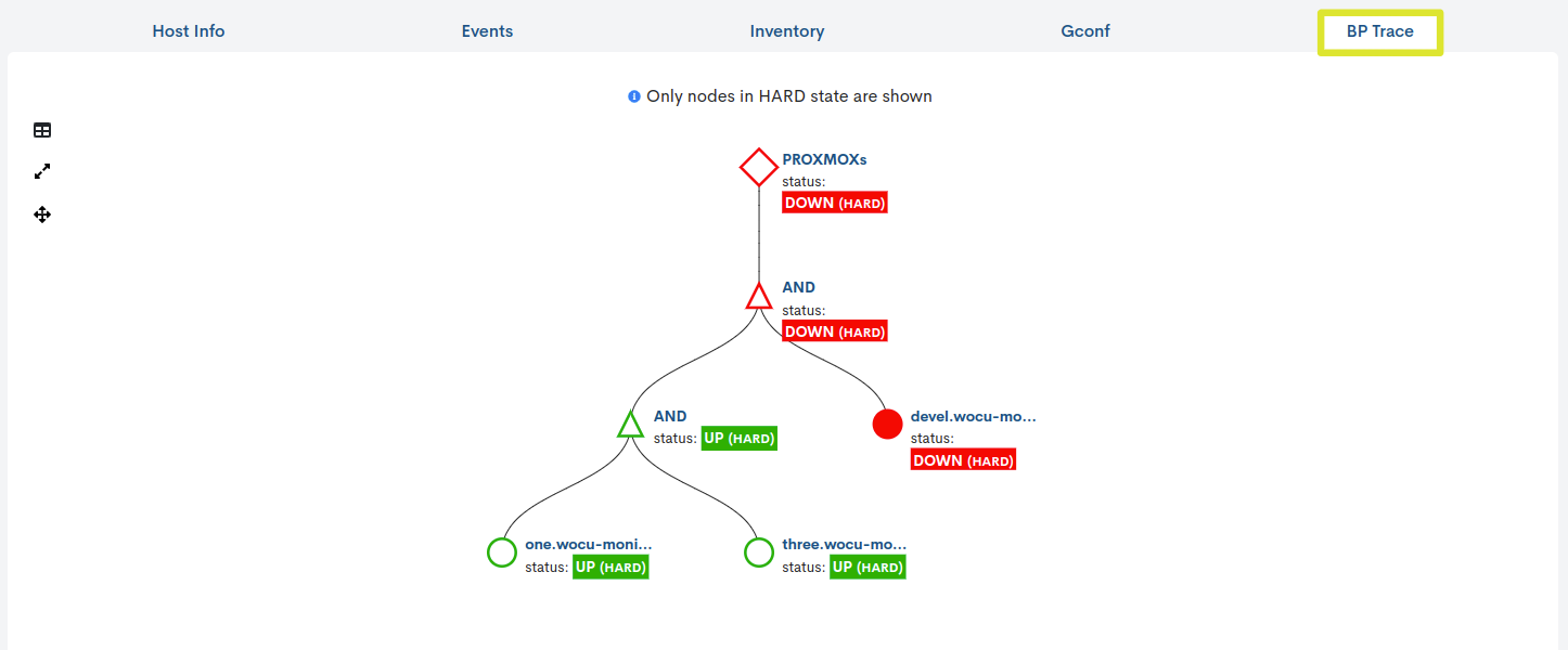
The BP Trace tab, visible only in the Detail view of Business Processes, shows the user a tree drawn to from a previously defined Asset Business Rule.Thanks to the representation with nodes and logical relationships, in addition to knowing the status of the Business Process, the user will be able to analyze and locate the root cause of an abnormal monitoring state.
Remember
Having established the Business Rule, WOCU-Monitoring will first evaluate the status of each Business Process element. Then, taking into consideration these individual states and the logical operators that link and relate the elements of the Business Process, the system will calculate and determine a state for the Business Process.
On the other hand, the system only considers states of type HARD to determine the overall state of the node. Therefore, any internal changes of type SOFT will be rejected and will not affect the monitoring state calculation.
Parts of the overview
1. Problematic Assets table
As the name suggests, this information table lists all assets that have a problem or failure, whether or not they are the cause of the total tree failure.
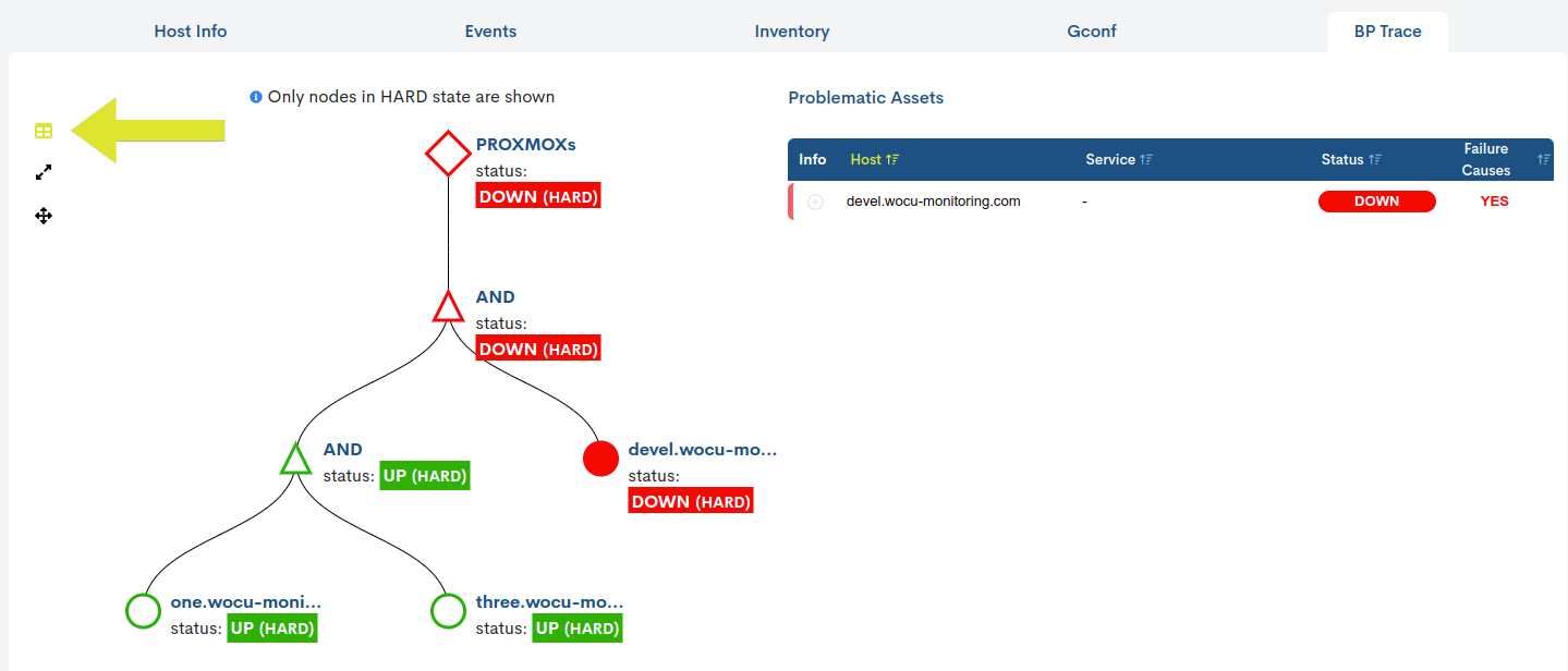
Each entry in the table records for a specific Host:
- Info Column: Only in the entries for Hosts with associated Services is the (+) button included, which displays a new entry in the table detailing the reason or motive for the problem that affects said service and, consequently, the possible cause of the fall or instability of the tree.
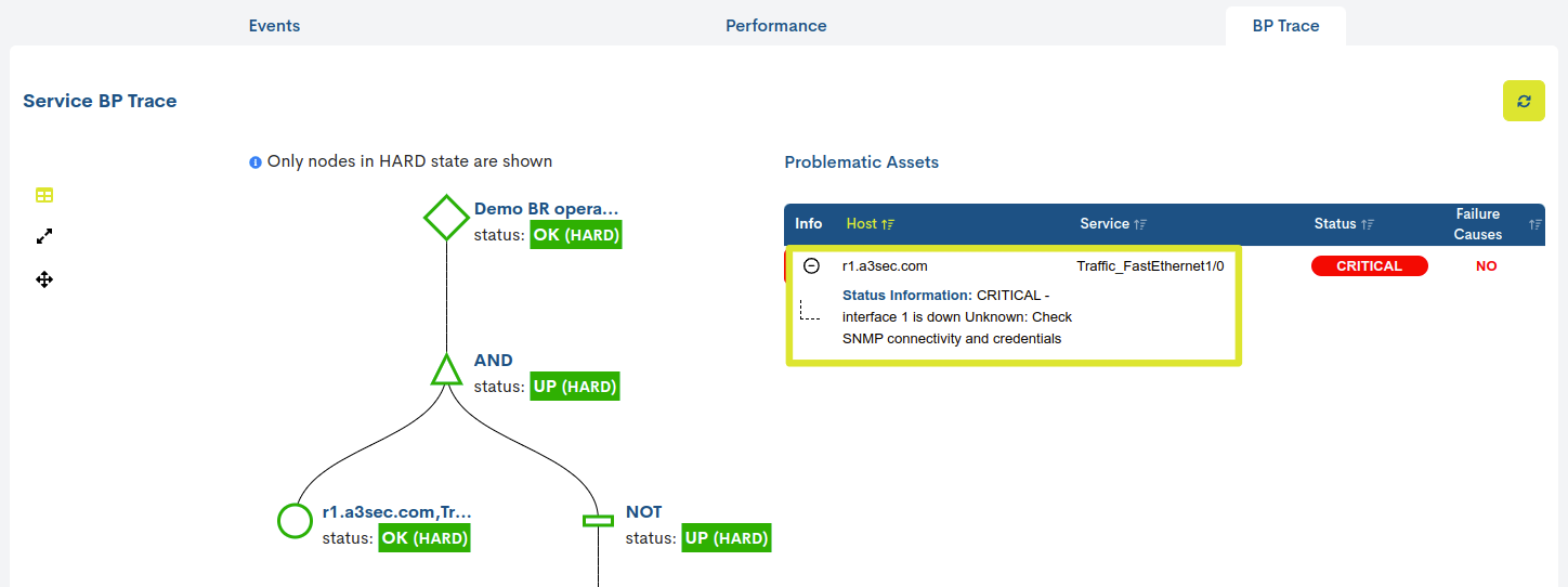
- Host column: each row is an anomalous Host, which may or may not be the reason for the crash or total failure of the painted Business Process. The displayed name is determined by the value of the
Display nameattribute.- Service column: service associated to a problematic Host.
- Status column: current monitoring status of the respective problematic Host.
- Failure Causes column: specifies whether this asset is causing the tree to fall (value = YES) or whether its problem is not affecting operational stability (value = NO).
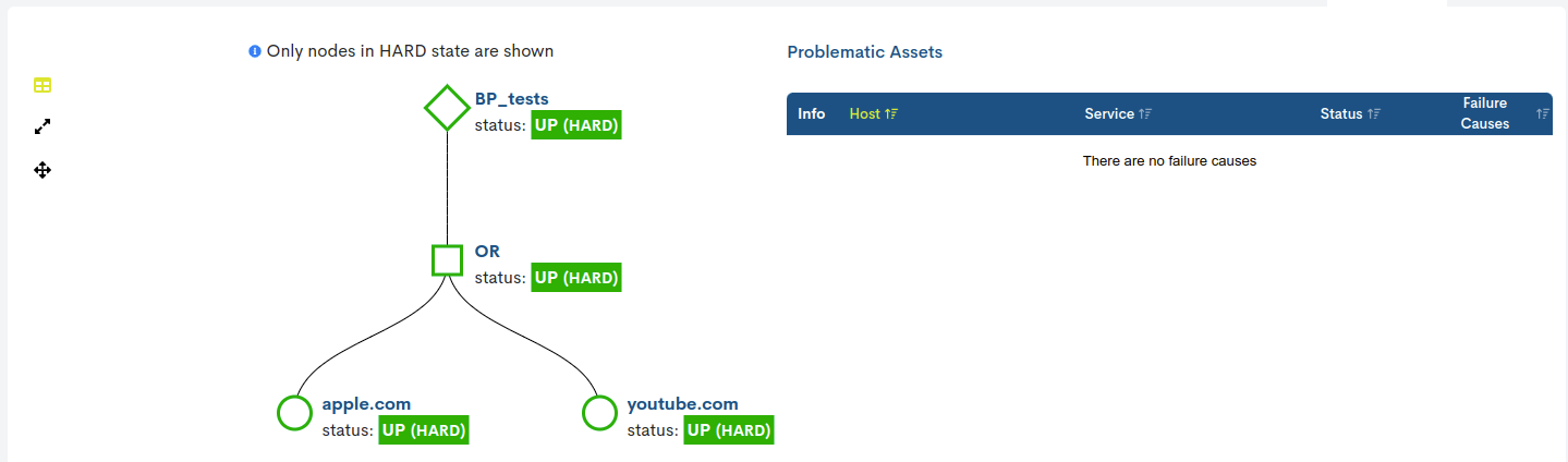
In case the Business Process has an optimal monitoring status, this table will be hidden (no data) and the tree will be displayed clean.
Important
As a special feature, please note that for duplicate problem nodes that are in the same situation, only a single entry will be recorded in the table. Remember that WOCU-Monitoring is able to process and render trees composed of several nested Business Processes (BP).
2. Business Process Tree
Tree representation of the Business Process Rule. This tree uses colour coding, shapes and labels to represent the status of each part of the process. The simplicity of this tree facilitates the analysis and immediate location of the root cause of the failure.
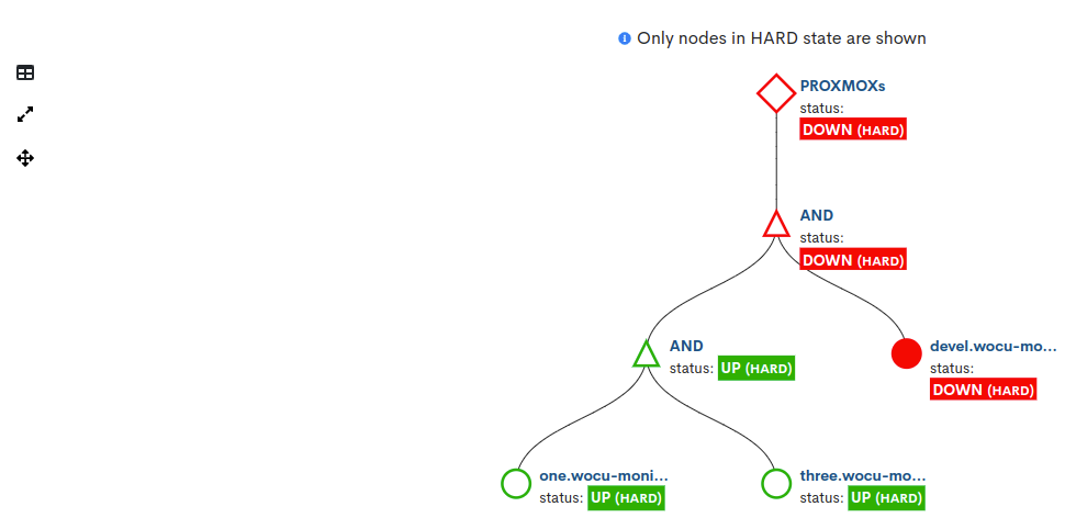
Issues to consider
The icons of the nodes correspond to their type. The relationships between them are represented with geometric shapes.
Icon
Description/Operator
Character

Hosts

Services

Hosts Business Processes

Services Business process

AND operator
&
OR operator
|
NOT operator
!
Operator OF
n of x, % of xThe colour of the tree nodes corresponds to their state:
Blue (Unknown)
Yellow (Warning)
Red (Critical/Down)
Green (UP/OK)
Each node is accompanied by an identifying label (determined by the value of the Display name” attribute) and its current monitoring status.
By clicking on the identification label of a node corresponding to a device or service, the system automatically redirects the user to its Detail view, where detailed data on events, associated configuration, and any relevant alerts are presented.
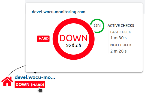
In addition, when you place the cursor over a node corresponding to a device or service, a pop-up window appears with updated information about:
Current monitoring status and duration: inside the central circle, the following is indicated: the status reported by the host and how long it has been in that state.
Monitoring check: Active Checks / Next Check: the small ON/OFF circle indicates whether active checks are enabled. The Next Check label shows the time remaining until the next scheduled verification.
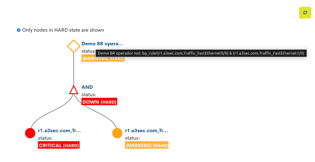
The node corresponding to the Business Rule will always head the tree. Placing the cursor over the node name will display the business rule as a visual aid to understanding the mapped tree.
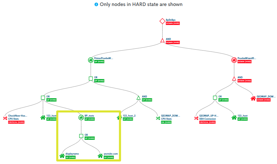
The tree also supports nested Business Processes (BP), that is, BPs that include other BPs among their members, whether they are BP Hosts or BP Services.
It is possible to expand and collapse nodes to make navigation through the tree more comfortable. To do this, just click on a specific node and the dependent nodes will be hidden, showing only nodes of hierarchical levels above it.
Tree display options
- Show/Hide table
The problematic assets table is hidden by default, leaving more space for the tree to be displayed. To display it, simply click on the table icon. It will be displayed immediately. To hide it again, repeat the action.

- Expand the tree
If any node is hidden, clicking on the icon with the arrows pointing to the ends will re-expand the tree view to show all of its nodes.
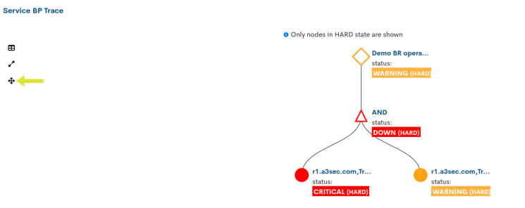
- Center tree
By scrolling with the mouse it is possible to manipulate the zoom in and out of the tree. The view can be centred immediately by clicking on the icon with two intersecting arrows.

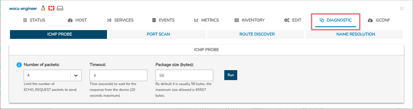
Diagnostic
The set of actions that make up this view allow for an in-depth analysis of the current functional and operational status of a Network Host, in order to detect any anomalous situation that has occurred and to identify its nature and reason for failure.
The diagnostic function is synonymous with technical analysis, which is indispensable for the prevention of incidents that could compromise the stability of the monitored network infrastructure.
Important
As a general rule, the Import-Tool will carry out and manage the following actions. In the event that the Host (object of the diagnosis) is linked to a poller, then this will be the one who proceed to run the diagnostic task instead of the Import-tool.
Note
The diagnostic function shall not be available in Business Processes views, as these processes can only be performed on physical machines (assets) and not on logical pools.
ICMP Probe
The ICMP Probe command is used to determine the status and connectivity of a Host. This protocol sends messages (ICMP Echos) to the Host to request a response and check if it has an IP connection, i.e. if there is communication at the network level.
In addition to determining this connectivity, the latency or time it takes for response messages to be received by the Host can be obtained.
The user must specify in the fields:
✓ Number of packets: the total number of packets you want to drop to diagnose the status, speed and quality of the communication. There is a sending limit of 10 packets.
✓ Timeout: time (measured in seconds) to wait for host response. Limited to a maximum of 20 seconds.
✓ Package size (Bytes): size (measured in bytes) of the packet sent via ICMP. Limited to a maximum of 65507 bytes.
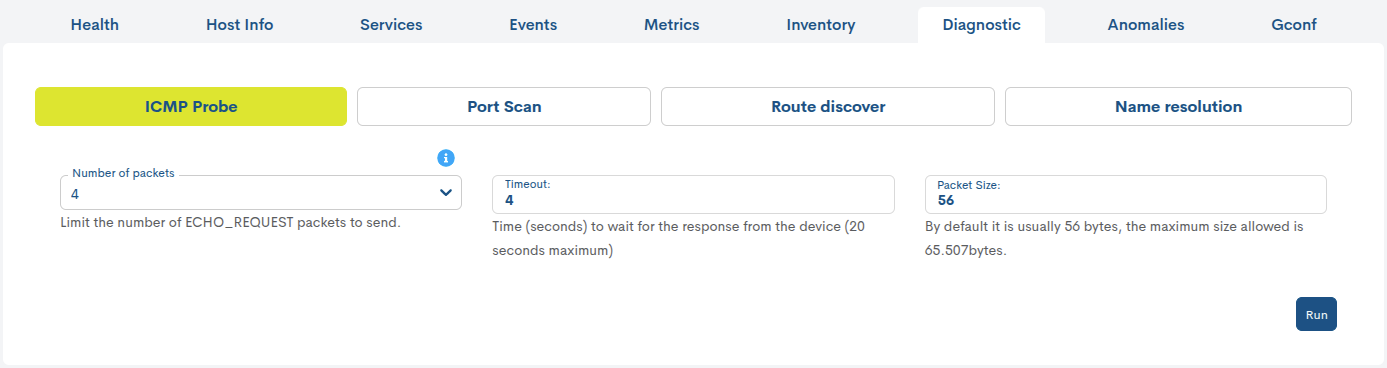
Once the request is loaded and processed (button Run), the system will display the following result:
✓ Set of statistical values resulting from the path of the set of packets, detailing the Round-Trip Average times, as well as the percentage of ICMP packets lost (Transmission Statistics).
✓ A graph constructed from the recorded response times of each of the packages.
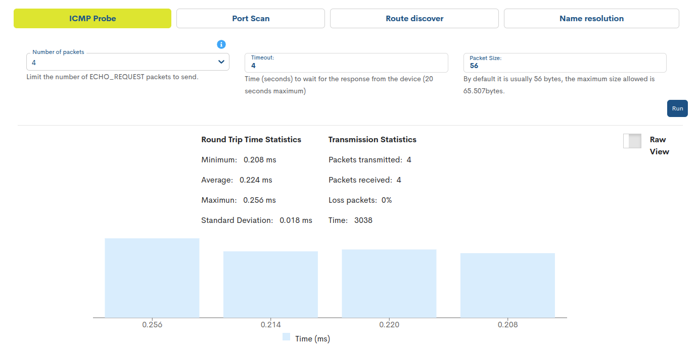
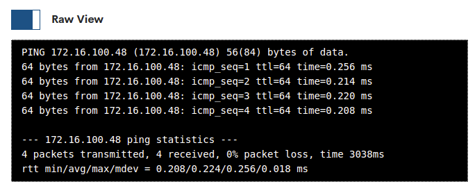
Activating the Raw View filter displays the raw output or response of the actual command launched and which WOCU-Monitoring captures in a table, graph or other formatted element for easy reading and understanding. By default, this component will be hidden, leaving more space for the rest of the data.
Port Scan
As the name suggests, this process runs a port scan on a Host to locate externally exposed Services, PING sweeps, operating system detection and version detection.
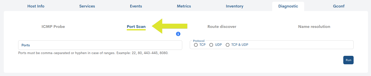
The user can add in the Ports field a separate port or combine with a range of them (separating each object by a comma). Next, the scan protocol to be executed must be selected. Possible options are:
TCP (Transmission Control Protocol): option ticked by default.
UDP (User Datagram Protocol): includes a 100 port limit. Higher requests will be declined.
TCP & UDP: combination of both protocols to optimally exploit each other’s strengths in data transmission.
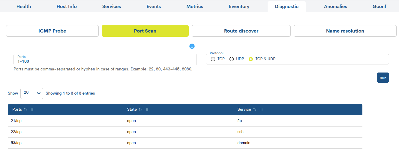
Once the action is launched (button Run), the system will display the result through a tabular format, where for each identified port (column Port) the following information is recorded:
✓ Column State: status of the port (open/closed).
✓ Column Service: service that is running that port.
Note
The table will show a maximum of 25 ports. This is a limitation of the internal program executing the action.
Activating the Raw View filter displays the raw output or response of the actual command launched and which WOCU-Monitoring captures in a table, graph or other formatted element for easy reading and understanding. By default, this component will be hidden, leaving more space for the rest of the data.
Route Discover
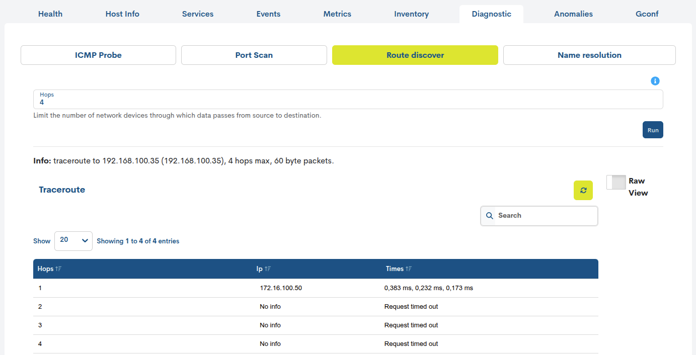
This task allows to know the route that a packet takes to reach its destination, i.e. how it is routed to the machine where the Host under diagnosis is hosted. As a result, a list is obtained of the machines that have been routed (firewalls, balancer, network to network, etc.).
The user can specify the number of hops to the final machine in the Hops field.
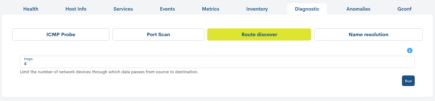
When the action is triggered (button Run) the system will display the following result:
✓ Information about the Host (IP) end of the route, maximum hops or stations recorded and network packet size.
✓ Through a tabular format, the following information is recorded for each recorded hop (column Hops):
✓ Column IP: where the packet is located just at that hop.
✓ Column Times: sending times for each of the three network packets sent (per hop or hop) to verify the consistency of the route.
Activating the Raw View filter displays the raw output or response of the actual command launched and which WOCU-Monitoring captures in a table, graph or other formatted element for easy reading and understanding. By default, this component will be hidden, leaving more space for the rest of the data.
Name Resolution
This function extracts machine identification information (address, email, manufacturer, etc.) by querying DNS servers.
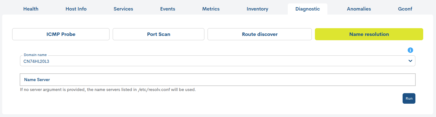
Its configuration is very simple:
✓ Domain Name: selection of the Host Name or Display Name of the Host about which information is to be obtained. If both terms match, only one option will be displayed.
✓ Name Server: server object of the query. If the field is not filled, the responsibility passes to the Import-Tool.
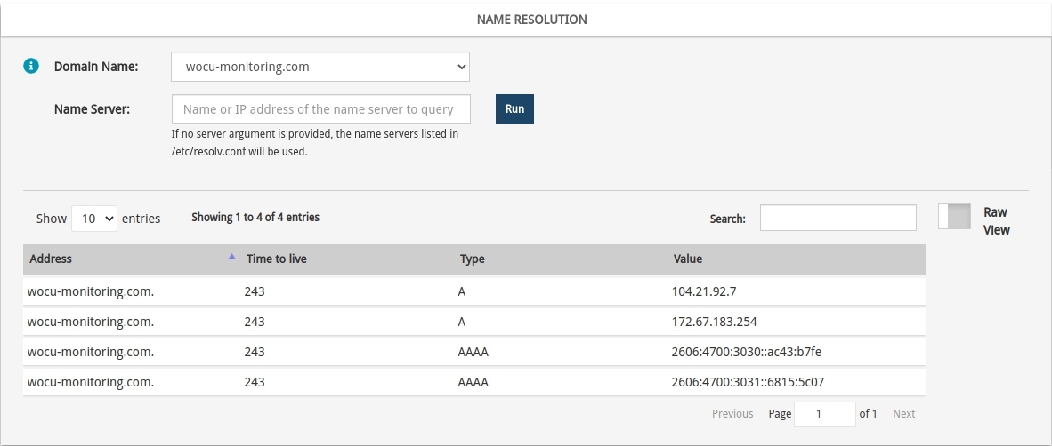
Once the action is launched, the system will display the result in a tabular format:
✓ Column Address: address for which information is obtained.
✓ Column Time to live: time for which the DNS record must be kept or maintained.
✓ Column Type: output type identifier. More information on the possible options here.
✓ Column Value: information extracted from the query made.
Activating the Raw View filter displays the raw output or response of the actual command launched and which WOCU-Monitoring captures in a table, graph or other formatted element for easy reading and understanding. By default, this component will be hidden, leaving more space for the rest of the data.
Anomalies
Attention
The Anomalies tab will be available when the Realm has the Observability enabled and anomaly analysis configuration exists for the Host metrics.
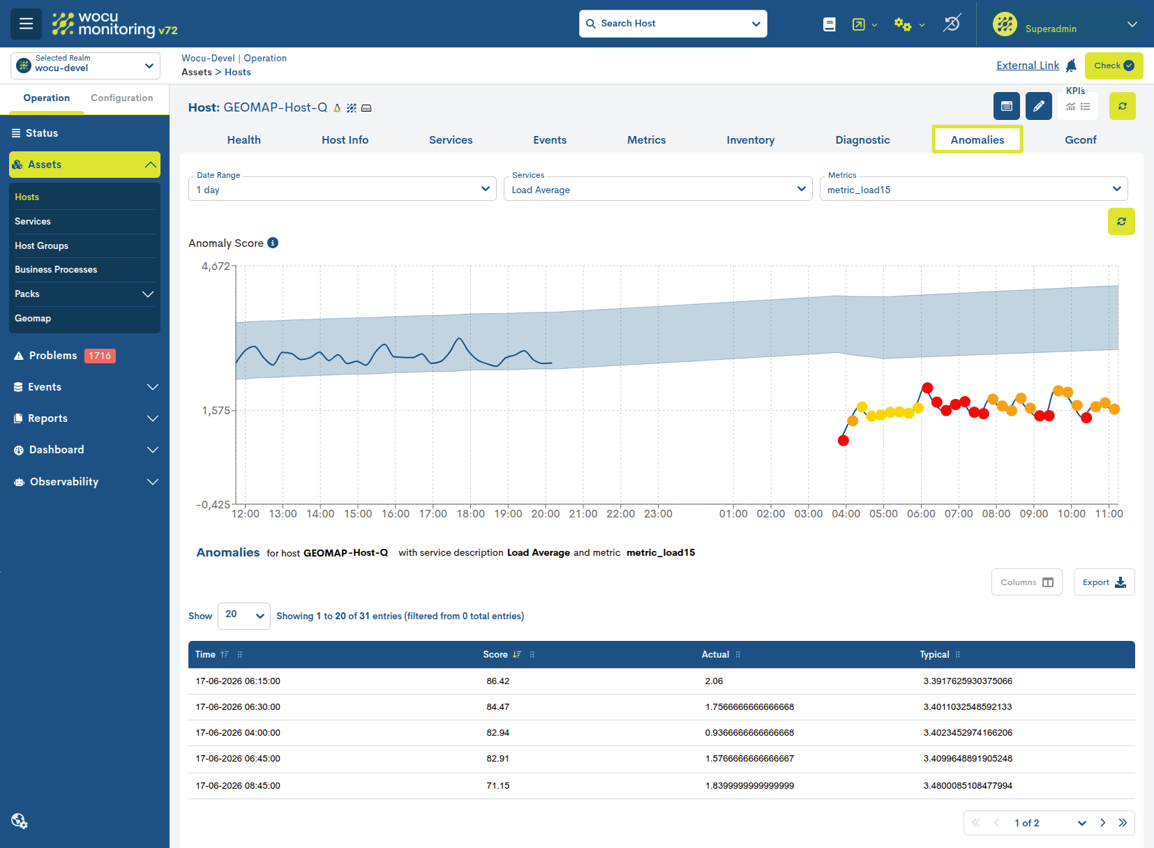
The Anomalies view allows you to view detected anomalies on the metrics of a monitored host in WOCU-Monitoring. It combines query filters, a graph showing the evolution of the metric, and a table detailing the detected anomalies.
This functionality is part of the Observability module and leveragesthe analytical capabilities of Elastic Observability. Using the data stored in Elastic, the time series of the monitored metrics are analyzed to identify values that deviate from the expected behavior.
Note
For detailed information about this view and its functionalities, see: Host Anomalies View.
GConf
Within the WOCU-Monitoring product suite, there is the Module GConf. The module for the comprehensive, unified management of the configurations of the network equipment managed and monitored in the application.
This technology allows us to have version control on any desired devices, storing backups of the configurations whenever required.
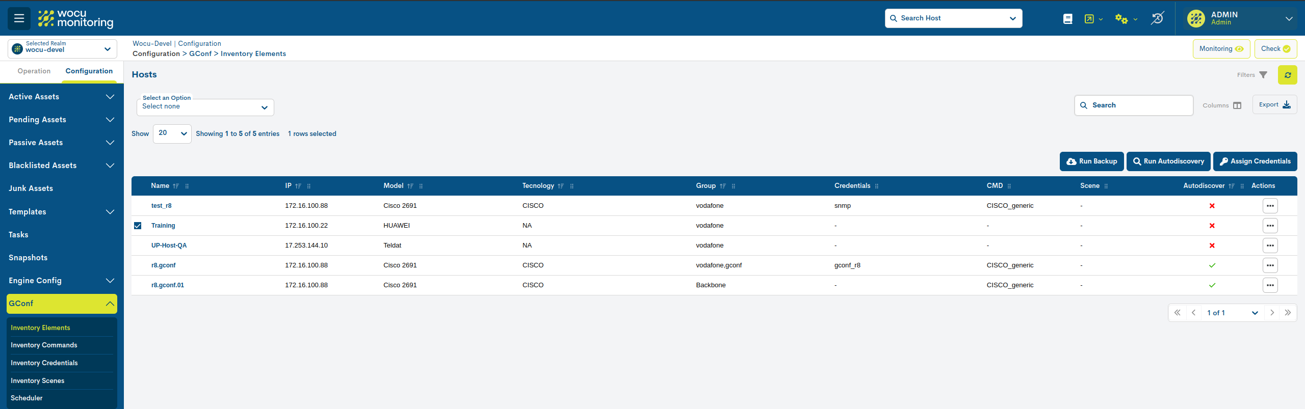
From the device details view, it is possible to view the backups recorded for that device. This section constitutes the first point of interaction with the Module GConf, from where other additional operations can be carried out.
GConf Available Configuration
In this table the backup copies (backups) of the registered configurations of the different monitored components.From this space it is possible to know the configuration in detail anddownload it.
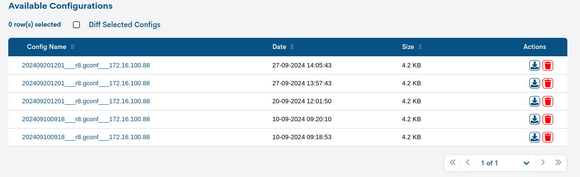
For each of the entries the following information is recorded:
1. Config Name: name of the registered configuration.
The format is as follows:
YYYYMMDDHHMM___name___IP, being YYYY the four digits of the year, MM those of the month, DD those of the day, HH those of thehour and MM those of minutes. Following the separator character (_), the name of the monitored component (router, port, etc.) is included andfinally, associated IP address.Acting on its identifier enables Detail view Available Configurations:
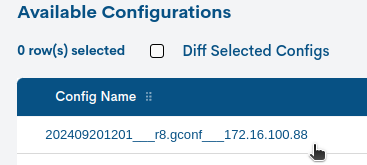
2. Date: exact date and time of the backup execution.
3. Size: indicates the size of the backup in kilobytes (KB).
4. File Type: indicates the file type. The possible values are:
CONFIG_PUSH: file containing new configurations, manually added from the management view Configuration Files.
BACKUP: file corresponding to a generated backup.
5. Is Unique: indicates that the backup contains a configuration different from previous ones and is kept as a unique reference in the history. Therefore, it is saved as a relevant reference point, since it reflects a new configuration state compared to previous backups that did not record changes.
The cell will display a tick when the file is considered unique and a cross otherwise.an X.
6. Actions: applicable actions on each backup:
Download (down arrow icon): Download the configuration file locally, for later use in case of loss, corruption, damage of the original data, etc.
Delete (trash can icon): Deletes the backup of the WOCU-Monitoring database.
Detail view Available Configurations
This view shows the complete configuration of the selected item.It is presented in raw form for easy reading and understanding.
This information corresponds to the configuration imported from the GConf tool.
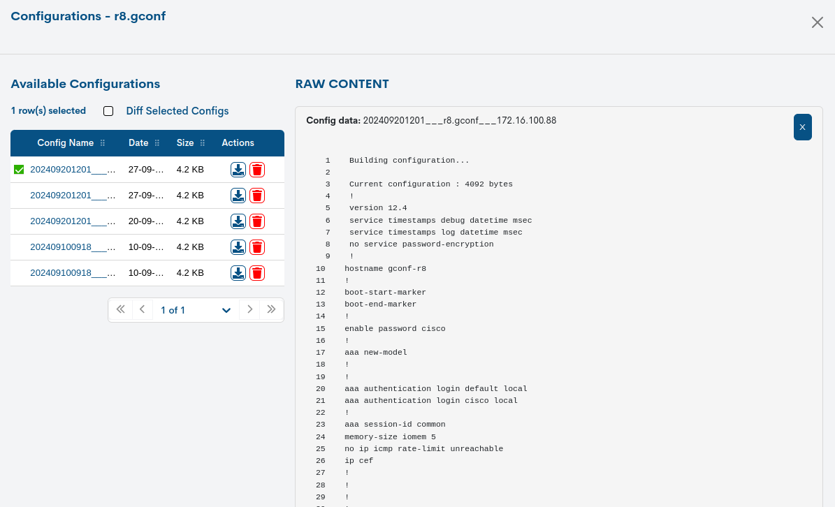
Diff selected configs
Selecting the Diff selected configs checkbox enables the ability to compare differences or discrepancies between two versions of stored configurations.
The values that have been deleted will be shown on the right side of the view with a red background color, and new values with a yellow background color.
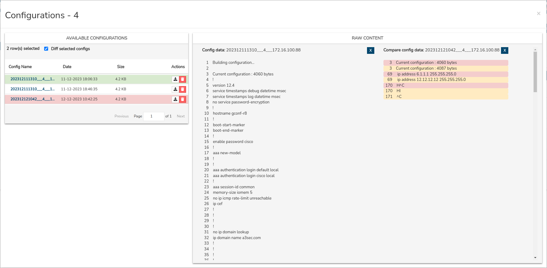
This function is valuable for understanding and tracking changes in the configuration over time, facilitating the detection of potential problems, conflict resolution, and effective management of the evolution of the monitored device’s configuration.
Show Only Unique Configs
By selecting the Show Only Unique Configs checkbox, the backup history will be filtered to show only unique (distinct) configurations.
A unique backup is one that is retained because it represents a different configuration compared to previous copies. When backups are performed periodically and no new or changes in the device configuration are detected, new backups do not replace the existing one, as they do not provide different information. In this case, the first valid backup is marked as unique.
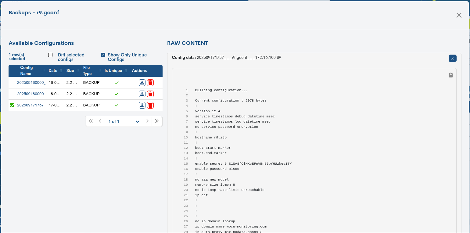
This state of uniqueness is maintained until a modification occurs in the asset’s configuration. At that point, the new backup generated will reflect these changes and will be considered a new unique backup within the historical record.
Actions on the Device
From this view, it is possible to execute monitoring actions directly on a specific device, without needing to access the general inventory. This functionality allows for quick and contextual operations, facilitating the daily management of the selected device. Furthermore, the availability of these actions is conditioned by the current state of the device, ensuring that only the operations permitted under the given circumstances are displayed and executed.
Note
These actions are the same as those present in Assets > Inventory of Hosts, ensuring functional consistencyacross the entire platform.
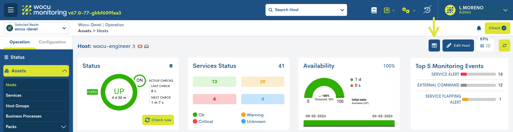
Pressing the button displays a selector showing all the actions that can be performed on that specific device.
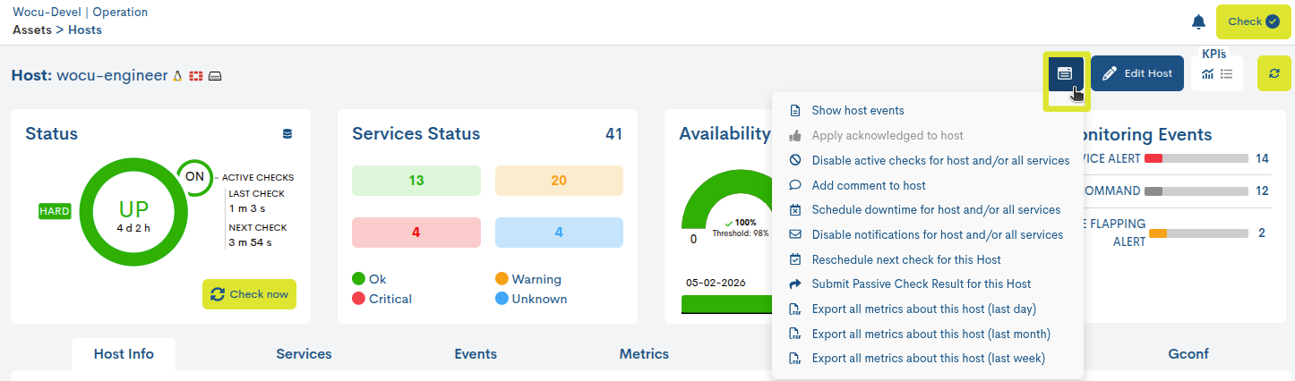
These are:
Export all metrics about this host: exports metrics associated with the device.
Important
Once the desired action has been selected, it is necessary to refresh the viewso that the system initiates the corresponding process and the changes associated with the executed action are reflected.
To facilitate operational monitoring, the representative icons for each action are displayed in the device’s host-status-panel KPI. These icons allow for quick identification of which actions are enabled or active at any given time, providing a clear view of the device’s operational status.
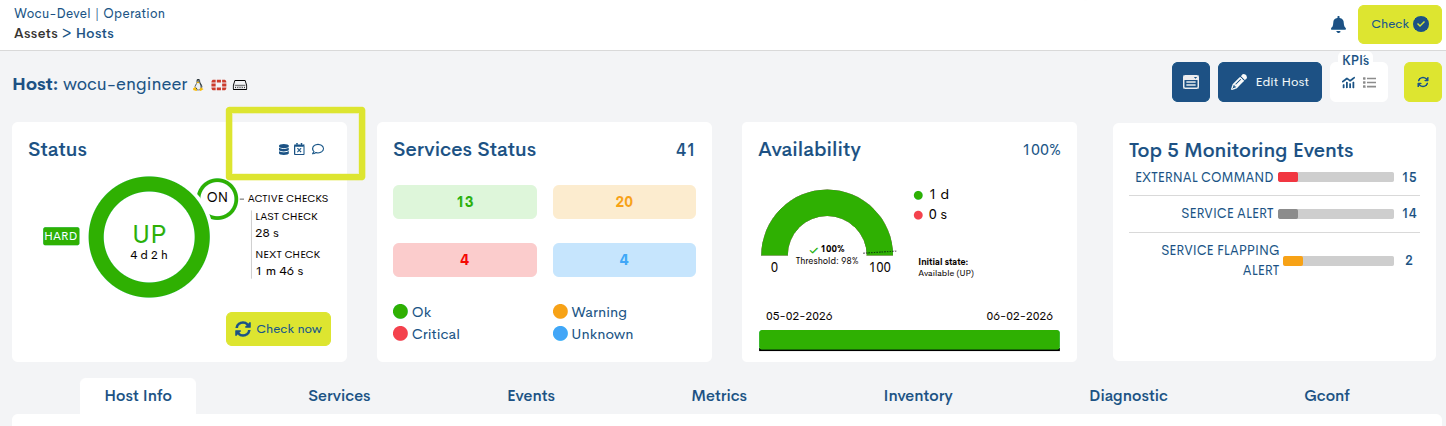
Edit Host
Through the Edit Host button located at the top right of the detail view, the user can make changes to the configuration of the host or BP in question.
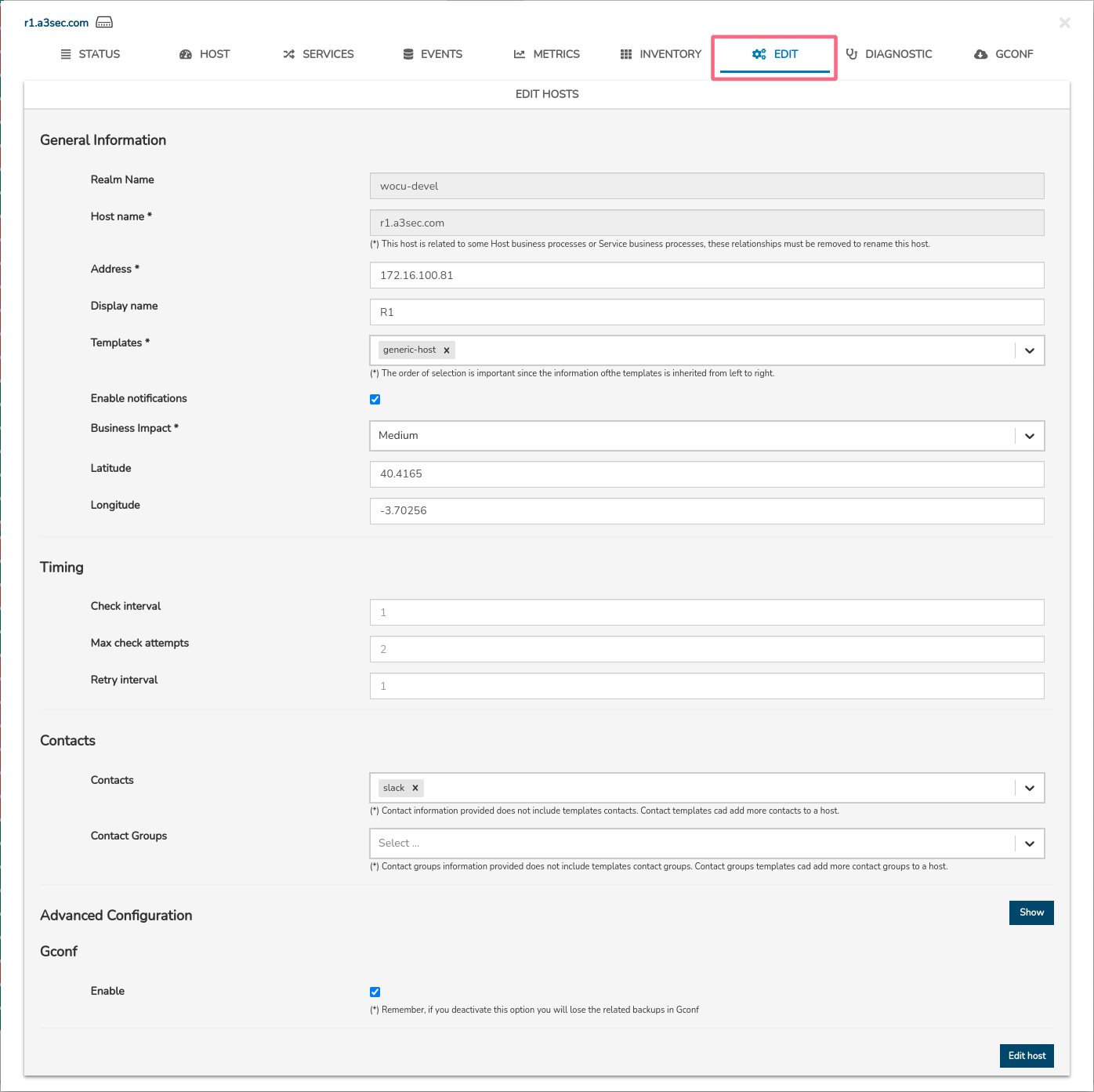
The following is the editing and configuration form for a host and a BP. The fields to edit match those described in Add Host and Add Business Process Host (+ Add).
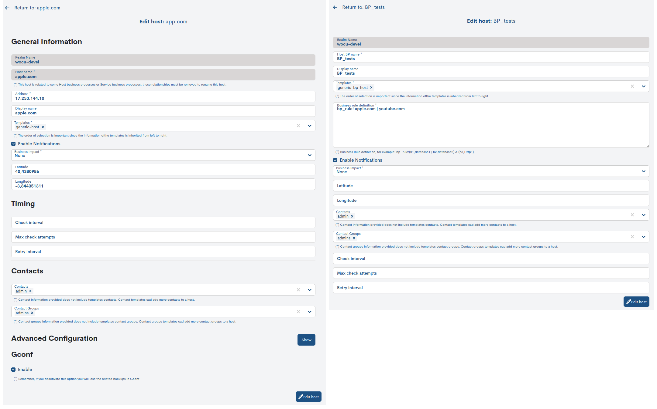
Important
The edit action will only be enabled on standard Realms, i.e. it will be hidden for Realms based on Host Groups and Multirealm.
Once the data in the corresponding fields has been modified, you will have to press the blue button Edit Host to save the configuration made up to that point, and you can continue editing the form.

Finally, any changes to asset configuration will be consolidated into WOCU-Monitoring through the execution of WOCU Check.
Warning
The system will return an error when trying to save the edit, when the Host has been previously deleted from the configuration module and the WOCU Check action has not been executed to make the permanent deletion of the Host effective.
This lack of synchronization between the configuration module and the editing module will cause an error preventing the modification of the asset, since it will not be detected as a member of any realm.
